


4
®
Installation
The installation of the Wizard USB Extender set is straightforward and can best
be achieved in most cases by following these stages for each module:
•
Mount the module
•
Connect the cables
Mounting a module – desk or rack
The Wizard USB Extender modules can be
situated on a desk (or floor) or alternatively, for
larger installations, mounted within optional
rack mount chassis units.
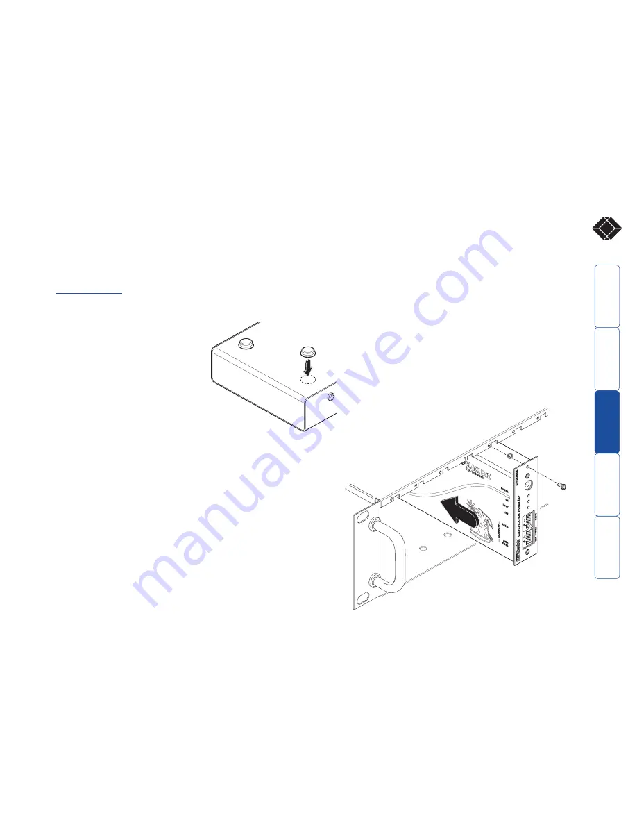
Desk mount
Apply the supplied self-adhesive rubber feet to
the underside of the module(s).
Rack mount
Note: The module switches are not accessible once it is inserted into the rack,
therefore, check all settings before insertion.
1 Place the supplied rack securing plate onto the front of the module and secure
it with the two countersunk screws.
2 Orient the module on its side so that its labelled face is the correct way up and
the securing plate is facing away from the rack.
3 Slide the module into the required rack position. The rectangular cut-out in the
front upper lip of the rack allows the two screws on the module’s upper edge to
slide through.
4 The rack mount chassis has a series of holes in its floor that are spaced to
accommodate the two screws on the module’s lower edge. Ensure that the
screws correctly locate into the two holes of the chosen slot. The rack securing
plate on the module should now be flush with the front of the rack mount
chassis.
5 Use the third (pan-head) screw, in the top hole of the rack securing plate to
fasten the module to the rack.
1
ON
4
2 3
SECT 3


