background image

3

2.  Remove cover and battery case.

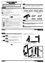
3.  Install Exterior Assembly.

a.

 Remove cover from assembly 

by sliding cover up and off, see 

figure. 3

b.

 Remove the battery case from 

interior assembly by lifting the 

case up and out and set aside, 

see figure 4.

Place the exterior assembly flush onto door, 

threading the wire harness under the latch.

Route the connector of the wire harness 

though the slot at top of mounting plate. 

Insert the long screws to engage exterior 

assembly. Tighten screws to secure - 

making sure that both the 

plate

 and the 

exterior assembly

 are 

flush

 against the door 

and vertically aligned


with the edge of door.

4.  Install Interior Mounting plate.

Insert the half round spindle through the latch 

fully - to engage with the  exterior assembly.

5.  Install the half round spindle.

Fig. 4

Fig. 3

Important before proceeding:


1. 

Verify that position #2 of the “Settings Switch” is in the 

OFF

 posi-

tion. (Refer to section 11.)  

2. 

Work with the door open (away from jamb) to avoid accidental 

lock out.  

Wire 

Harness

Half Round

Spindle

Connector

Long Screws

Mounting Plate

Summary of Contents for SmartCode 40490-01

Page 1: ...steps ATTACH CONNECTOR PROGRAM CODE S VERIFY OPERATION Section 6 Section 10 a b c Section 10 d 1 2 3 4 5 6 7 8 9 0 Copyright 2009 Black Decker Corporation 40490 01 SmartCode Lever Manual Program Button Mounting Holes Turnpiece Lock Button Cylinder Settings Switch Panel Keypad LED Cylinder Getting Started Installation Programming Manual Interior Assembly Interior Cover Half round Spindle Exterior A...

Page 2: ...mm slot See figure 2 For a drive in latch Align collar opening with shape of bolt and slide it on until the catch pins of latch snap into the pin holes of collar Install latch with the slant of bolt facing in the direction that the door closes Use wood block to install latch Note should collar require removal squeeze collar hard at sides and remove For a latch with face plate 1 Insert latch into b...

Page 3: ...ng screws to engage exterior assembly Tighten screws to secure making sure that both the plate and the exterior assembly are flush against the door and vertically aligned with the edge of door 4 Install Interior Mounting plate Insert the half round spindle through the latch fully to engage with the exterior assembly 5 Install the half round spindle Fig 4 Fig 3 Important before proceeding 1 Verify ...

Page 4: ...ate place the interior assembly on door aligning the spindles with the spindle slots of interior assembly 7 Install Interior Assembly b Once flush on door insert and tighten small screws to secure assembly onto the mounting plate Note To aid insertion of screws approach the screw holes with the screw loaded onto the screwdriver a Align the connector with the connector port of the interior assembly...

Page 5: ...gain this is the reverse of the normal direction c Install interior lever and tighten set screw clockwise e Insert the key into cylinder and rotate it clockwise to the horizontal position then press lever to seat into assembly With key still in the horizontal position tighten the set screw clockwise to secure the lever Set Screw on opposite side Latch Bolt d To install exterior lever first remove ...

Page 6: ...he locked position the exterior lever is still allowed to turn but it will not retract the latch When the unit is in the unlocked position the exterior lever will turn firmly retracting the latch for entry f Test the locking and unlocking function If you cannot lock the unit from the exterior or cannot rotate the interior turn piece proceed with the following steps to remedy the situation 1 Insert...

Page 7: ...eep twice and will require you to restart from step 10a Note Programming instructions can also be found on interior of lock a Press the program button on the interior unit once b Enter in 4 to 8 digit code onto the keypad c Press the LOCK button to save code d a Press the program button on the interior unit twice b Enter in 4 to 8 digit code onto the keypad c Press the LOCK button to save code d P...

Page 8: ...am button on the interior unit three times b Enter in 4 to 8 digit code onto the keypad c Press the LOCK button to save code d Press the LOCK button and re enter the code to test Unit should go to the unlocked position allowing exterior lever to retract the latch If it does not go to the unlock position repeat steps a through c Press the LOCK button and re enter the code to test Unit should go to ...

Page 9: ...d will flash red multiple times for approximately 3 seconds After a correct code is entered the unit beeps multiple times for ap proximately 3 seconds Regardless of switch 1 position under Low Battery condition red LED will flash every 5 seconds 1 The interior LED 2 The exterior Keypad when switch 3 is OFF 3 The Audio Indicator when switch 3 is in the ON position Note For future battery replacemen...

Page 10: ...ll 1 800 327 5625 for USA CANADA or visit www kwikset com For Weiser product call 1 800 677 5625 USA 1 800 501 9471 CANADA or visit www weiserlock com WARNING This Manufacturer advises that no lock can provide complete security by itself This lock may be defeated by forcible or technical means or evaded by entry elsewhere on the property No lock can substitute for caution awareness of your environ...

Reviews: