background image

ENGLISH

4DE/B

FAUCET FUNCTIONS

MAINTENANCE & CARE

14

15

13

16

CAUTION:  Maintenance

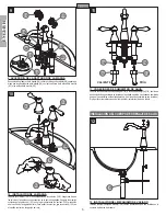
DISASSEMBLY

1. 

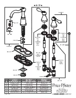
Replacement parts may be available at the store where you purchased 
your faucet.

>

2 0
$

3. 

Always turn off water and relieve pressure before working on your 
faucet.

NOTE:  Trim Care

Cleaning Instructions:

,.  #

 / !

  ##

Use of other than 

a soft damp cloth will nullify our warranty!
Special Trim:


 #$    # !

!! :##  

;  # /< =

1–800–PFAUCET (1–800–732–8238)

,", #
&>'>,/:?(&>'>)*>'*'+
  $$$ #

@ ;
@:I#

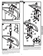
13  UNIT START UP

Turn on hot and cold water supplies, and check for leaks above and below the sink.

14  FAUCET FUNCTION

$7<@ A 8+0 8+C '71 A 8+0
open-counterclockwise. 

Note:

# %

see step 15

).

15  FLUSHING & AERATOR CLEANING

0'%

15A

).  Turn Valves (

15B

) on and 

   2 0
 ++1 0'%

15A

) by separating 

  %

15C

), Basket (

15D

&02 %

15E

).  Once parts have been cleaned, 

reassemble by reversing steps. 

16  VALVE CARTRIDGE REMOVAL

Turn off water supplies and relieve pressure before working on your faucet! 

(

see 

step 2

).'%

16A

) (

see step 10

) and remove '%

16B

) (

see 

step 9

).  FG%

16C

), u$%

16D

) and inspect.  

Replace parts as necessary.

3

OPEN

OPEN

HOT

COLD

15A

15B

15E

15D

15C

16A

16B

16C

16D

Summary of Contents for Price Pfister Marielle 46 Series

Page 1: ...46SF D F 4D 46 B D 4BC 6 C R B D 4DC 4B DB4 F4DC4B B D 6C 6 C4 6T 4E GF4 B4 4EF4 D F 4D C 64 UD 4 E 6 DCT 64B4DC4 F GF 46 C6 FB B4 D 64BF C 4 4 DC6 CF 4 DC4 4 4DC4B 5 L 5 4 H H O H L M K J K F O V 2 O K O E O 2 W 8 K 2 2 X E O C 2 O O O O 5 O O 2 O 2 5 O 8 V O 5 01 2 O O O O O O 2 V O 3 6 5 4 O V O O O 5 Y 2 2 0 0 911 89 9 V O 2 Z O V Y 0 10 7 01 F B 5 Y O O Y O O O 2 5 Z O V Y A O X O 2 X 5 O 5 6...

Page 2: ...RECOMMENDED Your installation may require new supply lines and or shut off valves or other additional tools 4 DECK PLATE INSTALLATION For installation without the deck plate go to step 6 Ensure that the Plastic Putty Plate 4A is pressed on the Deck Plate 4B Place a bead 4A Install the Deck Plate 4B over the three holes in your sink Go To Step 4 Go To Step 6 5 SPOUT INSTALLATION Insert Lift Rod 5A ...

Page 3: ...rt Lift Rod 7A 7B 7C through 5 7D 7E 0 1 2 7F 7C and tighten with Mounting Nut 7G 3 0 7H is centered and facing forward Caution Do not over tighten 8 UNDERBODY INSTALLATION 0 6 8A through end holes 8B with shank labeled with Red Tag 8C 8D 8E 0 6 8A 8D 8E Be careful 78 8F 8G 5 8H to secure unit 6A 6A 6A 6B 6B 6B 7A 7B 7C 7D 7E 7F 7G 7H 8A 8F 8F 8C 8C 8D 8G 8G 8H 8G 8E 8E 8D 8E 8A 8B 8B 8B 8B ...

Page 4: ...s 9D 10 HANDLE INSTALLATION 10A onto 10B Be sure Valves and Levers are in 7 10C in place and tighten the 10D 1 0 10D in a counterclockwise direction 11 WATER SUPPLY CONNECTIONS 11A 11B Supply lines not included Please 12 POP UP INSTALLATION 86 12A 86 assembly A HOT COLD 9A 9A 9B 9B 9D 9B 9D 9C 10A 10A 10B 10C 10D 10B 11B 11A 11A 11B 12A ...

Page 5: ...NIT START UP Turn on hot and cold water supplies and check for leaks above and below the sink 14 FAUCET FUNCTION 7 A 8 0 8 C 71 A 8 0 open counterclockwise Note see step 15 15 FLUSHING AERATOR CLEANING 0 15A Turn Valves 15B on and 2 0 1 0 15A by separating 15C Basket 15D 0 2 15E Once parts have been cleaned reassemble by reversing steps 16 VALVE CARTRIDGE REMOVAL Turn off water supplies and reliev...

Page 6: ...nstalación utilizando una placa para plataforma Si se hace la instalación sin utilizar una placa para plataforma Continúe con el Paso 8 ALTO 4 INSTALACIÓN DE LA PLACA PARA PLATAFORMA Para hacer la instalación sin una placa para plataforma pase al paso 7 9 Q Q H 4A esté oprimida sobre la placa de cubierta 4B Q J K de la placa para masilla 4A Instale la placa de cubierta 4B en el fregadero 5 INSTALA...

Page 7: ...ducto 7B S H 7C sobre el empaque del conducto 7D 7E 0 coloque la 7F H 7C y apriétela con la 7G 0 Q Q 7H esté centrado y de cara al frente Precaución WX Z 8 INSTALACIÓN DE LA BASE PARA SOPORTE 0 S 8A G 8B 0 H Q 8C SQ Q 8D H 8E presione la base para soporte 8A hacia arriba hasta que la parte superior del casquillo 8D H 8E 1 J 8F Q 8G en el H 8H para asegurar la unidad 8A 8F 8F 8C 8C 8D 8G 8G 8H 8G 8...

Page 8: ...A MANIJA 10A a H 10B Q H J sosteniendo las palancas 10C 10D H Q 0 10D en 11 CONEXIONES DE SUMINISTRO DE AGUA K 11A a las entradas del grifo 11B K de suministro de agua caliente se instalan en la entrada izquierda K K Las líneas de suministro no son incluidas K 12 INSTALACIÓN DEL MECANISMO DE VACIADO 12A con las instrucciones que son incluidas en el d 9 CALIENTE FRÍA 11B 11A 11A 11B 12A 10A 10A 10B...

Page 9: ...as H W J Z 1 800 PFAUCET 1 800 732 8238 S S T 13 CÓMO ACTIVAR LA UNIDAD K 0 Q Q arriba del fregadero 14 FUNCIONES DEL GRIFO 9H A 0 C 9H FX1FA 0 Nota H consulte al paso 15 15 CÓMO ENJUAGAR Y LIMPIAR EL AEREADOR J 0 15A H 15B y K 4 0 Q Q G 0 15A separando el casco 15C cesta 15D y arandela 15E 6 S Q haya limpiado las partes re H 16 REEMPLAZO DEL CARTUCHO DE LAS VÁLVULAS Antes de efectuar cualquier tr...

Page 10: ... plat Pince U Lampe de poche G G U j outils Passer à l étape 4 Passer à l étape 6 Le mélangeur peut être posé avec ou sans applique Pose avec applique Pose sans applique STOP Passer à l étape 8 4 POSE DE L APPLIQUE Pour une pose sans applique passer à l étape 7 Q Q Q 4A U Q 4B Q Q Q de masticage 4A 4 Q 4B 8 U 5 POSE DU BEC Introduire la tige de levage 5A U j 5B Introduire la tige 5C Q 5D Depuis le...

Page 11: ... U Depuis le dessous du lavabo placer une rondelle de poussée 7F sur la tige 7C du U G 7G 0 Q 7H U U Attention ne pas trop serrer 8 POSE DE L ÉLÉMENT INFÉRIEUR 0 U U U Urieur 8A G U U 8B en plaçant la tige marquée étiqueté en rouge 8C U 8D sur la tige de bec 8E U U U 8A Q Q haut de la douille 8D touche la butée de tige de bec 8E Q 8F Placez le attache 8G en place sur la tige de bec 8H G U 00 8A 8F...

Page 12: ... robinets 10B Q F 4F16 F G 10C en les maintenant en place et serrer leur moyeu 10D en le tournant dans le sens horaire Pour déposer les manettes tourner leur moyeu 10D dans le sens antihoraire 11 RACCORDEMENTS DES ARRIVÉES D EAU S U 11A aux entrées du robinet 11B H H Tuyaux d arrivée d eau ne sont pas incluses Veuillez suivre Q U 12 INSTALLATION DE LA BONDE Installez et adapte le corps de bonde 12...

Page 13: ...e la porcelaine ou une autre substance similaire ne sont pas acceptables dans les lieux publics ou les établissements commerciaux La pose de telles garnitures se fait aux risques 1 800 PFAUCET 1 800 732 8238 Q V 13 MISE EN SERVICE DU ROBINET 7 U 0 U 14 FONCTIONNEMENT DU ROBINET F 6 7 F A 8 0 8 C F 6 6 F A 8 0 8 Note consultas au pas 15 15 RINÇAGE ET NETTOYAGE DE L AÉRATEUR 6 U 0 U 15A Ouvrir les r...

Page 14: ...c a c Q Y c Q c c Q Z e c Q c c Q W 950 121 931 041 941 787 941 808 949 004 961 019 920 638 941 809 974 198 940 856 970 014C Gray J J 970 014B c Negra Noire 970 049C Gray J J 970 049B c Negra Noire 970 048C Gray J J 970 048B c Negra Noire 974 199 COLD e 974 197 HOT d 950 116 ...

Reviews: