BJM Pumps PGV 110 Installation, Operation & Maintenance Manual Download Page 17


17 

Part description 

Quantity per pump 

Impeller 

1 piece 

Shaft Seal 

1 set 

Bottom Plate 

1 piece 

Packing 

Full set 


8)  Overhauling procedure (refer to section 11 “Sectional Drawing”). 

  Perform the overhauling work with the pump kept in horizontal position. 

  Unscrew off the bolts (B1 in Sectional DWG) to separate the pump 

from the pump base (170). Then, lift up the pump using the lifting eye-

bolt (58). 

  Provided two wooden blocks of about 100mm square onto clean floor 

and put the pump thereon horizontally. 

  By this, the pump is ready for overhaul. Overhaul the pump in the 

procedure given below. 
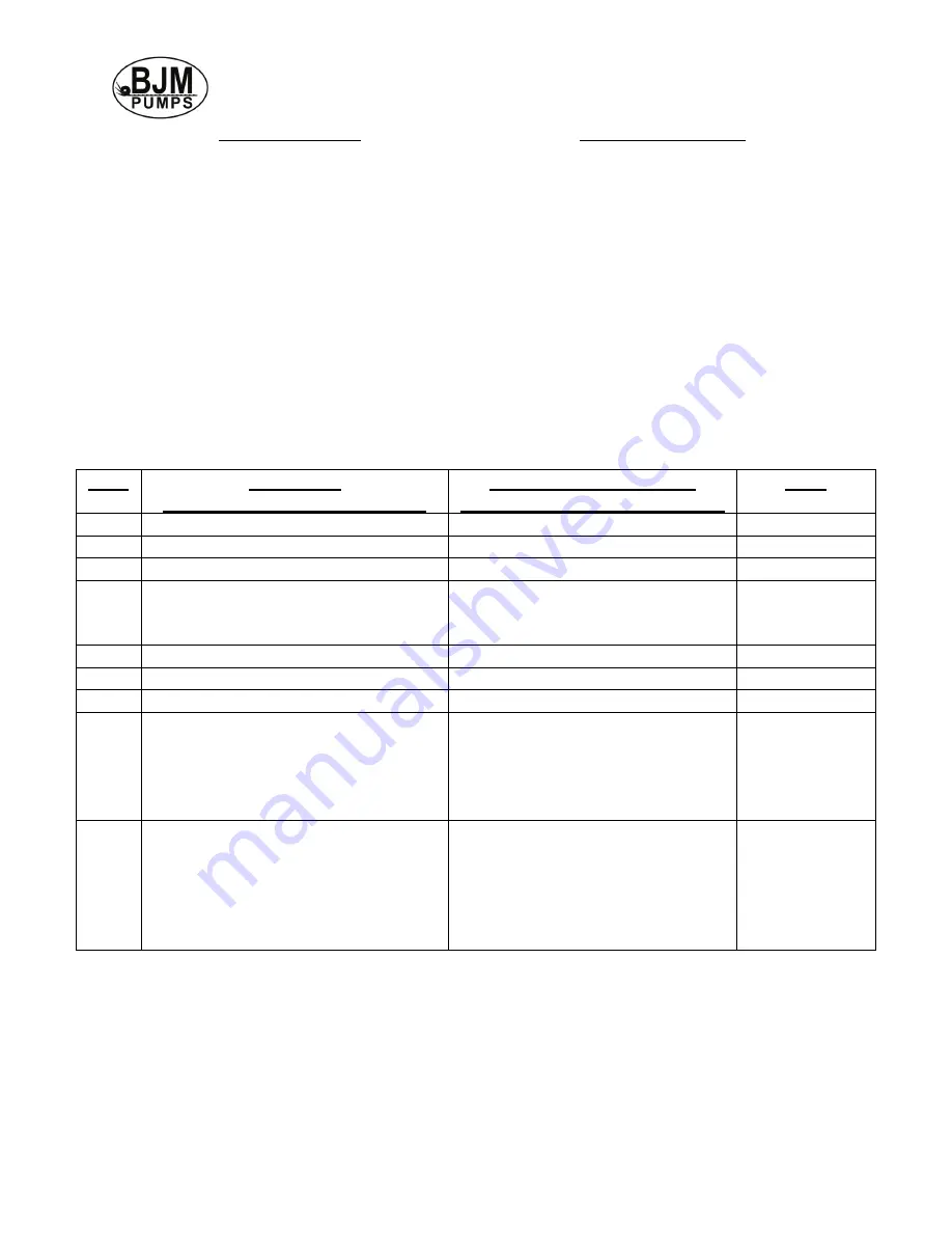
 

Step 

Part Name  

( ) : part No. in sectional DWG 

Overhauling Procedure  

( ): Part No. in sectional DWG. 

Note 

Strainer (16) 

Unscrew off stud nut (SN1) 


Bottom Plate (15) 

Unscrew off stud-nut (SN2) 


Impeller nut (B2) 

Unscrew off the nut 


Impeller (14) 

Draw off the shaft from shaft (8). 

Be careful not 

to damage the 

vanes 

Casing (13) 

Unscrew off stud nut (SN3) 


Drain-out of oil 

Remove oil plug (28) 

Follow 5.1 (1) 

Lower oil box (12L) 

Unscrew off stud nut (SN4) 


Shaft seal (10) 

After removal of the lower oil 

box (12L) in step 7, mechanical 

seal parts appear. Pull them out 

one by one from the shaft using 

a hooked-shaped puller. 


Upper oil box (12U) and rotor (7) 

Unscrew off stud nut (SN5) 

In this case, 

be careful not 

to damage 

stator coil, 

shaft and 

bearing. 


Summary of Contents for PGV 110

Page 1: ...Pumps CAST IRON Three Phase 460V PGV 55 PGV 75 PGV 110 Three Phase 460V PGV 220 Read this manual carefully before installing operating or servicing these pump models UObserve all safety information U...

Page 2: ......

Page 3: ...NG 8 INTENDED METHODS OF CONNECTION 9 THREE PHASE WIRING INSTRUCTION 9 PUMP OPERATION 11 MAINTENANCE AND INSPECTION 12 DISPOSAL OF PUMP 13 TROUBLE SHOOTING 13 ASSEMBLING 18 SECTIONAL VIEW OF PGV55 75...

Page 4: ...and performance curves is also available on our web site HUwww bjmpumps comU For assistance with your electric power source please contact a certified electrician Please pay attention to the following...

Page 5: ...ric power cable Death or serious injury could occur Never attempt to alter the length or repair any power cable with a splice The pump motor and pump motor and cable must be completely waterproof Dama...

Page 6: ...t a pump with machine connected using only the lifting rings of the pump Failure to observe this caution may cause injury or damage to the product Do not lift by cables Failure to observe this caution...

Page 7: ...TALLATION 1 Inspect each part component to verify that it is free of damage and imperfections 2 Do not lift or move the pump by the power cable Use the lifting handle or eye bolt attachment to support...

Page 8: ...ge to the pump or personal injury may result from alterations 1 Voltage and frequency check check whether the supply voltage and frequency meet those indicated on the pump name plate 2 Power connectio...

Page 9: ...ically operate a non automatic three phase pump a control panel is required Follow the instructions provided with the panel to wire the system for automatic three phase pumps see automatic three phase...

Page 10: ...ntry during temporary limited submersion and shall comply with the applicable requirements of the Standard for Enclosures for Electrical Equipment UL 50 or the standard for Metallic Outlet Boxes UL 51...

Page 11: ...n the specified liquid temperature For high temperature liquid specification refer to the catalogue Failure to observe this caution may cause injury For pumps with cutting mechanism never rotate in re...

Page 12: ...of high density water where sand slurry and other solids are much contained in the pumping of water the shaft power increases with increasing mixture density of solids and the motor is eventually ove...

Page 13: ...deral state and local regulations TROUBLE SHOOTING Disconnect the power source to the pump BEFORE attempting any type of trouble shooting service or repair Warning Pump will restart automatically when...

Page 14: ...vel or stop the pump 4 Small pumping rate capacity Reverse rotation of pump Interchange two wires of the cable for correct rotational direction Impeller clogged with foreign matter Remove foreign matt...

Page 15: ...ided with two oil plugs spaced at 180 from each other one is located upside from the shaft center and other located downside from the shaft center as illustrated in Fig 3 As illustrated in Fig 3 locat...

Page 16: ...on carefully inspect it when the suction pumping capacity decreases too Refer to section 6 4 Other Inspection check the bolts and nuts for loose damaged and deformation 5 Overhauling overhaul the pump...

Page 17: ...in the procedure given below Step Part Name part No in sectional DWG Overhauling Procedure Part No in sectional DWG Note 1 Strainer 16 Unscrew off stud nut SN1 2 Bottom Plate 15 Unscrew off stud nut S...

Page 18: ...seal packing with new ones Tighten securely bolts and screws with specific tightening torque After assembled turn the impeller by hand to check its smooth rotation After operation Maintenance When th...

Page 19: ...19 SECTIONAL VIEW OF PGV55 75 110...

Page 20: ...20 SECTIONAL VIEW OF PGV220...

Page 21: ...rd 201887 201880 201881 1 27 1 Bell Mouth 201891 201885 201886 1 27 2 Terminal Box 201924 201890 201890 1 27 2 1 O ring BUNA N 201895 201914 201920 1 28 Cable Packing 201899 201893 201894 1 28 1 Cable...

Page 22: ...using 201877 1 26 1 O ring BUNA N 201922 1 27 Power cord 201882 1 27 1 Bell Mouth 201887 1 27 2 Terminal Box 201891 1 27 2 1 O ring BUNA N 201924 1 28 Cable Packing 201895 1 28 1 Cable Washer 201899 1...

Page 23: ...IS EXPRESSLY AGREED THAT THIS SHALL BE THE SOLE AND EXCLUSIVE REMEDY OF BJM PUMPS LLC S DISTRIBUTORS AND CUSTOMERS UNDER NO CIRCUMSTANCES SHALL BJM PUMPS LLC BE LIABLE FOR ANY COSTS LOSS EXPENSE DAMA...

Page 24: ...r Condition of Cable Jacket New Good Fair Poor Rotation Direction of Impeller Rotation Use C W for clockwise CC W for counterclockwise Method used to check rotation viewed from bottom Resistance of ca...

Page 25: ...top Yes No Control Panel MFG model no Number of pumps operated by control panel NOTE At no time should hole be made in top of control panel unless proper sealing devices are utilized Short Circuit pr...

Page 26: ...hecked for leaks Yes No Do check valves operate properly Yes No Flow Does station appear to operate at proper rate Yes No Noise level Acceptable Unacceptable Comments Describe and equipment difficulti...

Page 27: ...NOTES...

Page 28: ......

Page 29: ......

Page 30: ...23 Spencer Plain Road PO Box 1138 Old Saybrook CT 06475 USA Phone 860 399 5937 Fax 860 399 7784 Email sales bjmpumps com Web Site www bjmpumps com Copyright 2008 2013 BJM Pumps LLC All rights reserved...

Reviews: