background image


Rev. 2.01 

- 30 -

SRP-350/352plusA&C

 Note: Minimum conductor construction must be stranded tinned copper. 

 
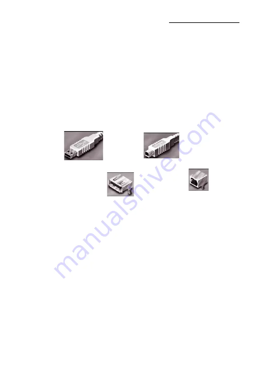
To minimize end user termination problems, USB uses a keyed connector protocol. The physical difference 

in the Series A and B connectors insures proper end user connectivity. The A connector is the principle 

means of connecting USB devices directly to a host or to the downstream port of a hub. All USB devices 

must have the standard Series A connector specified in this chapter. The B connector allows device vendors 

to provide a standard detachable cable. This facilitates end user cable replacement. 

Figure 2-10 illustrates the keyed connector protocol. 


Series A Connectors   

Series B Connectors 

Series A plugs are 

always oriented upstream 

towards the 

Host System


A Plugs 

(

From the 

USB Device

)

A Receptacles   

(

Downstream Output 

from the USB Host orHub


Series B plugs are 

always oriented downstream towards 

the 

U

SB 

Device


B Plugs 

(

From the 

Host System


B Receptacles 

(

Upstream Input to the 

USB Device or Hub


Figure 3-10 Keyed Connector Protocol 


The following list explains how the plugs and receptacles can be mated: 


• Series “A” receptacle mates with a Series “A” plug. Electrically, Series “A” receptacles function as outputs 

from host systems and/or hubs. 

• Series “A” plug mates with a Series “A” receptacle. The Series “A” plug always is oriented towards the host 

system. 

• Series “B” receptacle mates with a Series “B” plug (male). Electrically, Series “B” receptacles function as 

inputs to hubs or devices. 

• Series “B” plug mates with a Series “B” receptacle. The Series “B” plug is always oriented towards the USB 

hub or device. 


All manuals and user guides at all-guides.com

Summary of Contents for SPR-350plus

Page 1: ...Service Manual SRP 350 352plusA C Thermal Printer Rev 2 01 http www samsungminiprinters com All manuals and user guides at all guides com a l l g u i d e s c o m...

Page 2: ...the Memory Switches 14 3 Product Specifications 16 3 1 Appearance 16 3 1 1 Printer Dimensions mm 16 3 1 2 AC Adapter Dimensions mm 16 3 1 3 Feature Locations SRP 350 352plusA C TYPE 17 3 2 General Sp...

Page 3: ...uit 40 5 Disassembly and Assembly 41 5 1 Case lower block 41 5 2 Case Upper block 43 5 3 Frame block 45 6 Adjustments and Maintenance 48 6 1 Adjustment 48 6 1 1 Remaining Roll Paper Adjustment 48 6 1...

Page 4: ...ration Warning Never alter or add to the mechanical or electrical design of the ECR Unauthorized alterations might create a safety hazard Also any design changes or additions will void the manufacture...

Page 5: ...such elements to their original position 3 After servicing always check that the screws components and wiring have been correctly reinstalled Make sure that the portion around the serviced part has no...

Page 6: ...t ESDs are packaged with leads that are electrically shorted together by conductive foam aluminum foil or other conductive materials 8 Immediately before removing the protective material from the lead...

Page 7: ...Cable connector into the I F connector on the printer 3 Tighten the screws on both sides of the connector 4 Turn on the printer host ECR and Computer 2 1 4 Paper Roll Installation Figure 2 3 Cash Dra...

Page 8: ...e Main body 2 Attach the Plate Spring to the right side of Frame body and tighten a screw as illustrated 3 After assembling the Case lower to set Body Turn the Set over and attach the BRKT Hanger To t...

Page 9: ...01 9 SRP 350 352plusA C 5 Be sure that the BRKT attached properly to match the direction of arrow as follow and the BRKT Mount should be always fixed vertically All manuals and user guides at all guid...

Page 10: ...ge made with the power on have no effect and then on again Figure 2 5 Setting the DIP switches 2 2 2 Setting the DIP switch RS 232C Serial Interface DIP Switch 1 SW Function ON OFF Default 1 1 Auto Li...

Page 11: ...1 Baud rate bps Selection Transmission Speed 1 6 1 7 1 8 Default 2400 ON OFF OFF 4800 ON OFF ON 9600 OFF ON OFF 19200 OFF OFF OFF 38400 OFF ON ON 57600 OFF OFF ON 115200 ON ON ON 9600 Table 2 Print De...

Page 12: ...od is printed for each code that no ASCII equivalent Note During the hex dump all commands expect DLE EOT and DLE ENQ are disabled 5 When the printing finishes turn off the printer 6 Turn on the print...

Page 13: ...3 4 DARK Self test printing please press the FEED button ASCII 0 1 2 3 4 5 6 78 9 0123456789 A 0123456789 AB 0123456789 ABC 0123456789 ABCD 0123456789 ABCDE 0123456789 ABCDEF 0123456789 ABCDEFG 01234...

Page 14: ...2 850 Multilingual OFF OFF OFF ON ON OFF Page 3 860 Portuguese OFF OFF ON OFF OFF OFF Page 4 863 Canadian French OFF OFF ON OFF ON OFF Page 5 865 Nordic OFF OFF ON ON OFF OFF Page 16 1252 Latin I OFF...

Page 15: ...h Function ON OFF 1 External buzzer control This functions operate only after cutting External buzzer enable External buzzer disable 2 4 Reserved Fixed to OFF 5 Printing width 2 inch 3 inch 6 2 Color...

Page 16: ...ations 3 1 Appearance 3 1 1 Printer Dimensions mm Figure 3 1 Printer Dimension 3 1 2 AC Adapter Dimensions mm Figure 3 2 Adapter Dimension 115mm 65mm 35mm SRP 350plus SRP 352plus All manuals and user...

Page 17: ...Lower 4 Label Control 5 Push Button 6 Cover Cutter 7 Power Button 8 Bracket Dip Switch 9a Parallel interface IEEE 1284 9b Serial interface RS 232C 9c Ethernet interface 10BASE T 9d 10 DC Power Jack 11...

Page 18: ...d Parity Are determined by DIP S W position Interface Parallel Mode 1 Forward Mode Compatibility Mode 2 Reverse Mode Nibble Byte Mode Connector 36 Pin Centronics Ribbon Type USB Transfer Type BULK Spe...

Page 19: ...3 AOI Electronoics Print Method Thermal Line Printing Dot Density 0 125 mm 8 Dots mm Printing Direction Unidirection with friction feed Printing Width 72 0 2mm 576 dot Position Character Line 48 Font...

Page 20: ...P350 62 m Kansaki Specialty Paper Inc USA 2Color PB 670 75 m Mitsubishi PD750R 75 m Oji paper Mfg Co Ltd 3 3 4 Reliability and Environment Specification Item Description Remark Life Mechanism Monochr...

Page 21: ...49 c 72mm 0 2mm 2 83 0 0079 d 2 75mm 4 25mm e 2 75mm 4 25mm Dots 576 Font 9X24 64 Character Font 12X24 48 Character d e position can be shifted while printing according to the paper position 3 3 6 TPH...

Page 22: ...S L T 0 63 ml Line Supply Energy 0 34 mJ Dot Tsub 25 Supply Voltage 26 4 V Vp 28 0V Vp Peak of VH Substrate Temperature 70 Thermister Temperature Number of heating dots at same time 320 Dots Logic Sup...

Page 23: ...V In rush Current Max 40A Peak to Peak Line Regulation 24V 1 Load Regulation 24V 5 Ripple Noise Peak 300mV O C P Over Current Protect 3 0A 8 0A S C P Shot Current Protect Fold Back Method Table 3 12 P...

Page 24: ...Baud Rate 2400 4800 9600 19200 38400 57600 115200 Bps Data Word Length 8 bit Parity None Connector DB25P Female I F PBA Table 3 14 RS 232C Specification Note The HandShaking Flow Control Data Word Le...

Page 25: ...its a data to the host after confirming this signal 4 When XON XOFF flow control is selected the printer does not check this signal 7 Signal GND Signal Ground 20 DTR Output This signal indicates wheth...

Page 26: ...flow control 3 5 2 IEEE1284 Parallel Interface Bidirectional parallel interface in accordance with the IEEE1284 Nibble Byte mode 2 5 2 a Forward Mode Specification Compatibility mode Data transmissio...

Page 27: ...rinter nAck PtrClk PtrClk 11 Printer Busy PtrBusy Data3 7 PtrBusy 12 Printer Perror AckDataReq Data2 6 AckDataReq 13 Printer Select Xflag Data1 5 Xflag 14 Host nAutoFeed HostBusy HostBusy 15 NC ND ND...

Page 28: ...ame Assignment Color Function Shell Shield Drain Wire Frame Ground 1 VBUS Red Host Power DC5 V 500 mA 2 D White Differential Data Line 3 D Green Differential Data Line 4 GND Black Signal Ground Table...

Page 29: ...nd international safety testing agency requirements e g UL CSA BSA NEC etc for electronic signaling and power distribution cables in its category American Wire Gauge AWG Nominal Conductor Outer Diamet...

Page 30: ...s oriented upstream towards the Host System A Plugs From the USB Device A Receptacles Downstream Output from the USB Host orHub Series B plugs are always oriented downstream towards the USB Device B P...

Page 31: ...2 Cable Connection Pin No Description Direction 1 Frame GND 2 Drawer Kick Out Driver Signal 1 Output 3 Drawer Open Close Signal Input 4 24V 5 Drawer Kick Out Driver Signal 2 Output 6 Signal GND Table...

Page 32: ...R HEAD 16 17 15 13 11 9 7 21 19 14 12 10 8 20 18 CN8 AUTO CUTTER 3 1 4 2 CN7 3 1 2 4 FEED MOTOR CN6 POWER SWITCH 1 2 CN1 POWER ADAPTER 1 2 CN2 CASH DRAWER 3 5 1 2 4 6 CN9 1 2 3 4 U S B 3 1 2 CN12 PAPE...

Page 33: ...P SWITCH CIRCUIT DRAWER COMPULSORY SWITCH DRIVER MCU uPD70F3170 CLOCK 5MHz RS 232 DRIVER RS 232 CON IEEE 1284 DRIVER IEEE 1284 CON SENSOR CIRCUIT P_END NEAR SENSOR DRIVER SWITCH AUTO CUTTER A_CUT SWIT...

Page 34: ...e sources and TPH Driving Voltage 2 Voltage 7 8V CPU Download Voltage Change the input 24V to 7 8V by a regulation U1 LM2575S ADJ 3 Logic IC Driving Voltage 5V Change the input 7 8V to 5V by a regulat...

Page 35: ...nder Power on Reset circuit uses a reset ASM811REUSF T U8 When 3 3Vdc is fallen under 2 7Vdc by Power off reset signal prohibits the system from miss operating by lowering down to 0V Figure 4 4 Reset...

Page 36: ...pening cash drawer and driven by the Q10 Q11 2SD2170 When its state is high level signal Q10 or Q11 2SD2170 drive the solenoid to open the cash drawer As an optional item we provide sensor switch we c...

Page 37: ...CPU recognize the I F PBA by the value of the three return signal I F PBA MD0 MD1 MD2 RS 232C L L H IEEE1284 H H H USB2 0 H L H ETHERNET L H L No Connection L L L 4 3 5 RS 232C Communication Block Dia...

Page 38: ...ble Byte Mode The Centronics is Forward and the Nibble Byte are reverse Mode Figure 4 10 IEEE1284 Communication Block Diagram 4 3 7 USB Communication Block Diagram The printer support the USB Universa...

Page 39: ...1 2 3 4 5 6 7 8 RA9 10K 1 16W 1 2 3 4 5 6 7 8 0 RA12 10K 1 16W 1 2 3 4 5 6 7 8 DIP_B 0 SW2 218 008LPS 1 2 3 4 5 6 7 8 16 15 14 13 12 11 10 9 R64 100F 0 0 SW1 218 008LPS 1 2 3 4 5 6 7 8 16 15 14 13 12...

Page 40: ...e Thermal Printer Then the Data of both Shift Register 1 and 2 256 2 512 Bits are moved to the Latch Register After that the CPU sends a Strobe Signal to the Thermal Printer Then the Printer outputs t...

Page 41: ...crw 3x8 1 Foot Rubber 4 Brkt Dip Switch 2 Case Lower 3 1 Remove the three screw 2 Sparate the BRKT Dip switch Case lower Foot Rubber from the Printer 1 Remove the connector wires from main PBA and sub...

Page 42: ...r Cover Cabel 2 1 1 Remove the Screws form the BRKT PBA 2 Separate the BRKT Interface 3 Remove the two screws 4 Separate the BRKT Interface from the I F PBA Assembly 5 Separate the I F PBA from the Ma...

Page 43: ...screws 3 Separate the Cover open 4 Separate the Cover cutter 5 Remove the screws 1 Remove the two screws 2 Lift the Case upper in the direction of an arrow during pushing the Push button 3 Remove the...

Page 44: ...pring tension the Shaft hinge and the E Ring 3 Remove the E Ring 4 Separate the Bushing and the Roller Platen Assembly Spring Hook 1 Brkt Hook 4 2 Screw 3x4 4 3 1 Remove the Spring Hook two screws 2 S...

Page 45: ...1 Remove the three screws 2 Separate the Fixed cutter from the Cover Housing 3 Remove the two screws 4 Separate the Cutter Blade from Fixed cutter 5 Remove the two screws 6 Separate the Cover plate fr...

Page 46: ...e it Screw 3x4 4 Plate ground 2 Brkt TPH Rear Heat Sink 6 Screw 3x4 1 Spring TPH 5 Connector 7 3 1 Remove the screw 2 Separate the Plate ground and BRKT TPH Rear 3 Remover the two screws 4 Separate th...

Page 47: ...Release 5 Lever Release 4 Washer Slip Frame Main 1 Remove the screw And separate the Control board from the Frame Main 2 Remover the Washer slip 3 Separate the Lever Release from the Frame Main 4 Rem...

Page 48: ...change the setting to the upper or Lower position as described below Note The factory setting is based on a paper roll core with an outside diameter of 18mm If you use a paper roll with a core with a...

Page 49: ...on to make the cutter initialized and then open the cover open 2 In case that the cutter is not initialized remove the cover cutter then remove the paper jam with turning the knob to the arrow directi...

Page 50: ...beginning the cleaning 1 Open the cover open 2 Clean the thermal element the area that looks like it is marked a thin black line of the thermal head with a cotton swab moistened with an alcohol solven...

Page 51: ...1 Check the Harness of Power S W 2 Check the related Circuit Pattern 1 Check the TR Q3 Q4 2 Check the related Circuit Pattern 1 Check the Regulation U2 BA17805FP E2 2 Check the related Circuit Patter...

Page 52: ...t Pattern on PCB 3 Program download again 1 Check the Main Clock 5MHz 2 Check the Address Data Pattern 3 Check the Main PBA System Problem N N N Y Y Y SRAM Ok 1 Check the CS Signal 2 Check the SRAM 3...

Page 53: ...Problem N N Y Y LED Ok 1 Check the LED Signal from CPU on Main PBA 2 Check the Harness Signal VCC GND 3 Check the related Circuit Pattern Component 4 Replace the Panel PBA N Y Near End Ok End 1 Check...

Page 54: ...be 1 Strobe 2 2 Check the Harness 3 Check the related Circuit Pattern N Y End 1 Check the Signal MOT_PHA1 MOT_PHA2 on CPU 2 Check the Current Control Signals MOT_I01 MOT_I11 MOT_I02 MOT_I12 MOT_PS on...

Page 55: ...e Output Signal of U13 TA8428K 3 Check the Harness 4 Check the Auto Cutter Assembly Motor Cutter N Y Compulsory Failure End 1 Check the Compulsory Harness Connector 2 Check the Micro switch in the Dra...

Page 56: ...P_A C 2 Check the Input Signal DIP_IN1 IN2 3 Check the related Circuit Pattern Dip Switch Problem N Y I F PBA Select Ok End 1 Check the Diode on I F PBA 2 Check the Input Signal MD0 MD2 3 Check the re...

Page 57: ...r short 3 Check the Txd Rxd Pin on CPU 4 Check the MAX232 Driving Chip and related Circuit on I F PBA 5 Check whether Signal is affected by the Cable Noise RS 232C Problem Y N H W Handshake 1 Check th...

Page 58: ...ailure End 1 Check the Control Line CS_P 2 Check the 1284 Control Line and Status Line 3 Check the Signal of ICs U1 U3 U4 U5 4 Check the 1284 Cable whether it is open or shot 5 Check the related Circu...

Page 59: ...e and Signal 3 Check the Connector 34P 4 Check the Clock 30MHz 5 Check the related Circuit Pattern on Main PBA USB Problem Y N Reverse Mode Failure Y N 1 Check the Clock 30MHz 2 Check the Host whether...

Reviews: