


CT-110-2
9
• the SE-i1 is retrofitted.
• the SE-i1 as a replacement for SE-C1 is upgraded to
the full functionality of the SE-i1.
5.1.1
Mounting of the pressure transmitter to CS.
compressors
During all mounting work:
WARNING
The compressor is under pressure!
Serious injuries are possible.
Depressurize the compressor!
Wear safety goggles!
Connection positions see table 2, page 9.
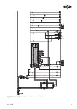
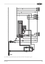
The following drawings show the connection positions
and the mounting using a CS.95 compressor as an ex-
ample. The positions of the connections 2 (LP) and 3
(LP) can vary, depending on the compressor. For
CS.65 .. CS.85, see dimensional drawings in the bro-
chures SP-171 (CSH) and SP-172 (CSW).
For the CSHP compressors, the SE-i1 is delivered sep-
arately as a basic sensor kit (part number 347 050 02).
It must be installed, wired and connected in the sys-
tem's switch cabinet, The cables between compressor
and switch cabinet must be protected by a fuse in the
terminal box. The fuse layout depends on the cable
cross-section and the applicable application-related
standards and can therefore not be universally spe-
cified.
High pressure transmitter
• First, screw in the T-piece into the connection posi-
tion 2 (HP) at the compressor.
• Then, screw the high pressure transmitter to the T-
piece and connect the sensor cable.
7/16-20 UNF
1 (HP)
1/8-27 NPTF
2 (HP)
Fig. 3: CS.95 compressor: Mounting of the high pressure transmitter
Connection positions CS. compressors
1
High-pressure connection (HP)
2
Additional high pressure connection (HP).
Connection for high pressure transmitter
3
Low pressure connection. Connection for low
pressure transmitter
4/8
Oil sight glass / connection for opto-electronic
oil level switch (OLC-D1-S)
5
Oil service valve
12
Oil temperature sensor (PTC)
Tab. 2: Connection positions CS. compressors, pressure transmitters
and NTC sensor
Summary of Contents for SE-i1
Page 54: ...Notes...
Page 55: ...Notes...