background image


www.bitrek.com.ua 


[email protected] 

+380 44 507 02 07


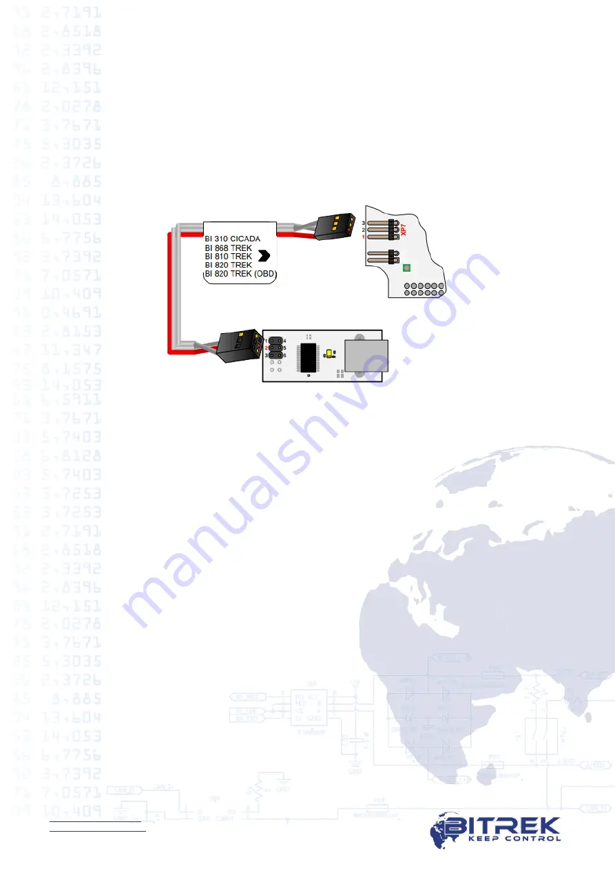
Connection to a Computer 


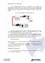
The  tracking  device  can  be  connected  to  a  computer  for 

configuration  and  servicing.  The  device  has  UART  output  interface  for 

that purpose. In order to connect the device to a computer a USB-UART 
adapter  should  be  used  that  can  be  purchased  from  the  dealer  as  an 

option. 


Fig. 3. BI-810 TREK Connection Diagram 


A terminal program can be used for data exchange with the device. 

Terminal configuration settings: bit rate – 115,200 bps, data bit – 8, stop 

bit – 1, without parity check, without stream control.  

Once the link is up, the device will start sending its status data to 

the terminal. Using the terminal program, a user can send commands to 
the device and receive responses to them. But the device first needs to 

send access password to the terminal in the following format:  


TPASS: password;  
 

where 

password 

is  an  access  password  for  the  terminal  (by  default, 

11111 is used).  

Once  sent,  the  password  will  be  valid  for  60  seconds.  After  this 

timeout,  the  password  needs  to  be  sent  again  so  that  the  data  can  be 

exchanged with the device. 


Indicators Description 


The  top  panel  of  the  tracking  device  has  3  LEDs  that  indicate 

current status of the device.  


Summary of Contents for BI-810 TREK

Page 1: ...k com ua sales bitrek com ua 380 44 507 02 07 95 C Otradny Prospekt Kiev 03061 Ukraine phone 38044 507 02 07 fax 038044 507 02 02 www bitrek com ua sales bitrek com ua 95 C Otradny Prospekt Kiev 03061 Ukraine Phone 38044 507 02 07 Fax 38044 507 02 02 www bitrek com ua sales bitrek com ua Vehicles Tracking Device BI 810 TREK Operating Manual Version 2019 09 1 ...

Page 2: ...oning 8 Installation Guide 8 Electrical Connections 8 Connection to a Computer 9 Indicators Description 9 List of SMS Commands 10 Structure of the SMS Commands 10 Configuring the Device 11 Detailed Description of Information Commands 13 Detailed Description of Controlling Commands 15 Basic Device Configuration 16 Security Settings 16 Configuring I O Components 17 Configuring Alarms 21 Description ...

Page 3: ...erved Warranty The warranty period for the tracking device shall be 12 months of the date of commissioning The commissioning date must be recorded per requirements set forth in the certificate for the tracking device if no such data are available in the certificate the warranty period shall be counted starting with the tracking device shipment to the customer Manufacturer s warranty shall only be ...

Page 4: ...re recorded and stored in the internal log that is based on a non volatile memory chip Records from this log are transferred to the operator panel through a GSM channel with a predetermined frequency or on an event basis Information exchange is done via GPRS and SMS Voice communication is also supported On line terminal operation is only possible provided there is GSM coverage Beyond the GSM netwo...

Page 5: ... 15 Full load amperage of discrete outputs 0 5 А 16 Number of analog inputs 2 17 Analog input voltage range from 0 V to 27 V 18 Power DC 19 Voltage from 6 v to 40 V 20 Normal input current 12 V 60 mA 21 Max current 12 V 350 mA 22 Non volatile memory capacity 2 MB or 65 000 entries 23 Internal battery Li Ion 1 000 mAh 24 Operating temperature from 30 С to 80 С 25 RH 80 15 26 Dimensions W х L х H 85...

Page 6: ...rted into the device Contacts of the SIM card must not be saved PIN code must be disabled a SIM card with an enabled PIN code can be used provided that the PIN code has been entered into the device settings To insert a SIM card all device connectors must be disconnected and its top cover must be removed There is a slot on the top of the circuit board Then the device has to be reassembled in the re...

Page 7: ... is 12 VDC or 24 VDC 2 Black GND Power Ground earth 3 Yellow Vout Power Secure power input for extra sensors Voltage Vin 350 mA max 4 Oragnge A Input Output A signal RS 485 5 Green B Input Output B signal RS 485 6 Blue Ignition Input 1 active discrete input Reserved for ignition 7 Brown DAT_low 1 Input 0 active discrete input 8 Pink DAT_low 3 Input 0 active discrete input 9 White A_in 1 Input Anal...

Page 8: ...tive battery terminals ATTENTION When performing welding operations during repairs of a vehicle MAKE SURE to disconnect power cable and periphery cables Discrete inputs with active 0 respond to connection of these inputs to GND ground This input is inactive when it is not connected input is blank Discrete inputs with active 1 respond to the voltage of over 8 V on them connection of the input to th...

Page 9: ...ps data bit 8 stop bit 1 without parity check without stream control Once the link is up the device will start sending its status data to the terminal Using the terminal program a user can send commands to the device and receive responses to them But the device first needs to send access password to the terminal in the following format TPASS password where password is an access password for the te...

Page 10: ...he device troubleshooting potential errors configuring the settings etc An SMS command should be sent together with login and password the sender s number must be included to the list of authorized contacts when such list is used Structure of the SMS Commands Any SMS with commands includes login password pair when configured and a list of different commands The commands are delimited with semicolo...

Page 11: ...one numbers is enabled SMS commands will only be performed provided that they have been sent from one of the authorized phone numbers login password is also required if enabled If there is no authorized phone number enabled SMS with commands will be received from any phone number Configuring the Device The BI 810 TREK Tracking Device can be configured by one of the methods below 1 Using a direct c...

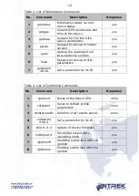
Page 12: ...om internal device sensors yes 6 flush Request for device profile parameters yes 7 getparam Get a parameter by its ID yes Table 4 List of Controlling Commands No Command Description Response 1 cpureset Reset of the device CPU none 2 rstallprof Reset to default profile parameters none 3 deleterecords Deletion of all records saved none 4 setparam Set a parameter by its ID yes 5 boot Update of device...

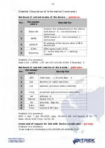
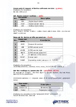
Page 13: ...rk Example of a response Data Link 1 GPRS 1 IP 46 133 143 201 GSM 5 Roaming 0 Retrieval of current location of the device getstatus No Parameter name Description 1 GPS Valid data 1 Invalid data 0 2 Sat Number of visible satellites 3 Lat Latitude previous known latitude 4 Long Longitude previous known longitude 5 Alt Altitude m 6 Speed Speed km h 7 Dir Direction degrees 8 Date Date 9 Time Current G...

Page 14: ...me Description 1 IMEI Modem ID number 2 APN GPRS access point 3 LOGIN GPRS access login 4 PASS GPRS access password 5 IP IP address of the server 6 PORT Server port 7 MODE Operating mode always 0 TCP IP Example of a response 353976012555151 internet none none 212 47 99 62 12050 0 Get the readings by parameter ID getparam ID consists of 4 digits the first digit is a profile number the last three sp...

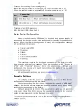
Page 15: ...example set the ID 0242 parameter value setparam 0242 www kyivstar net No Parameter name Description 1 Param ID Parameter ID 2 New Value New value of a parameter Example of a response to the setparam 0242 www kyivstar net command setting an APN Param ID 0242 New Val www kyivstar net Device firmware update BOOT Command parameters HOST IP address of the server containing the update PORT Port of the ...

Page 16: ...ce communication Roaming The settings required for the basic operation of the device include data transfer and tracking settings They are included to the Server GPRS and Tracking groups Once the appropriate settings are configured the device will start transmitting the data of its current location to the server All configurable settings are given in Addendum 1 Security Settings To comply with the ...

Page 17: ...are supported by the device If this feature is used the device will receive only SMS from the authorized phone numbers saved to its memory If SMS login and password are enabled they must be included in each SMS with the commands Configuring I O Components The BI 810 TREK Tracking Device can collect process and send data obtained from different sensors to the server Each sensor is an I O component ...

Page 18: ... 5 monitoring going beyond range 6 monitoring going within beyond range 7 event generation by change of an input by a preset value 8 event generation by change of an input by a preset value monitoring 5 Averaging constant 0 Clarifications to Table 5 Parameter 0 enabling disabling I O component transmission to the server Parameter 1 Priority low high When selecting the Priority low option the data ...

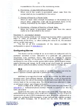
Page 19: ...nsor readings comes within such configured range In all other cases the event will not be generated and no information will be sent to the server Example Lower threshold of input voltage is set to 0 V the upper threshold is 10 V 10000 mV If the input voltage decreases lower than 10 V the event will be generated Figure 4 Fig 4 Generation of the Event by Going Within Range 1 Going beyond range An ev...

Page 20: ...hen actual input voltage goes off the limits of a configured range the event is generated Figure 6 Fig 6 Generation of the Event by Going Within Beyond Range 3 Monitoring When this mode is selected the data will be transmitted continuously and no events will be generated 4 Monitoring Going Within Range When a Going Within Range event is generated actual value from the sensor starts to be transmitt...

Page 21: ...particular I O component constitutes such condition Voice calls must be enabled in general configuration settings of the device I O component must be enabled configured to one of the events going within range going beyond range going within beyond range its ID must be set as a trigger for outbound calls and an authorized phone number Phone0 must be configured Note Outbound call can only be made or...

Page 22: ... Selection Enable ID 0917 1 In this mode the device tries to register on the enabled network set by the entire list of enabled networks parameters ID 0020 0059 If the SIM card is detected and ready the list of enabled operators is checked The device scans for available networks If networks are detected that are included to the list of enabled ones the device tries to register on one of the enabled...

Page 23: ... enabled networks setparam 0100 GPRS login setparam 0101 GPRS login setparam 0139 GPRS login Specify GPRS passwords of enabled networks setparam 0140 GPRS password setparam 0141 GPRS password setparam 0179 GPRS password ATTENTION If you specify the list of enabled operators but do not specify APN GPRS login GPRS password for each of them the device will not work in roaming Configuring the Device f...

Page 24: ...m the level meters as well as the data processed with Kalman filter Optimal filtration factors for Kalman filter are set by default Filtered and non filtered values are transmitted by different I O components Moreover if the level meters are equipped with an in built temperature sensor data from it can be retrieved and transmitted to a server Also when fuel level meters are used on special machine...

Page 25: ...figuration example Enabling the use of a backup server setparam 0196 1 IP Host2 setparam 0188 111 1 111 11 Port2 setparam 0189 11 Configuring Engine Lock The BI 810 TREK Tracking Device together with a normally closed relay can be used to lock the engine of the vehicle Lock is enabled by sending an SMS message to the device Example of the SMS command for locking engine DOUT1 setdigout 1 To unlock ...

Page 26: ...end the response ignitionon To disable the ignition lock the following command is used ignitionoff When the lock is disabled the device will send the response ignitionoff ATTENTION The ignitionon ignitionoff commands will be performed by the device provided that they have been received via SMS message ...

Page 27: ...st1 0188 none String Backup server IP address none IP or DNS 31 28 163 20 ipsPort1 0189 none 2 Byte Backup server PORT none PORT 20127 APN 0242 none String GPRS access point none APN gps utel ua Usname 0243 none String GPRS access login none User Name none Uspass 0244 none String GPRS access password none User Password none Send Period 0270 none 2 byte Transmission to server time sec 0 65535 60 Co...

Page 28: ...nable Dist Period 0901 none 1 Byte Enabling distance of retrieval none 0 disabled 1 enabled 1 Enable Angle Period 0902 none 1 Byte Enabling azimuth of retrieval none 0 disabled 1 enabled 1 Day Period 0903 none 2 byte Enabling time of retrieval with the ignition on sec 0 65535 30 Night Period 0011 none 2 byte Enabling time of retrieval with the ignition off sec 0 65535 30 Dist Period 0012 none 2 by...

Page 29: ...eration meter 0 1 sec 0 65535 50 Stop Move Timeout 0285 none 2 byte Timeout for movement stop by acceleration meter 0 1 sec 0 65535 200 Axel Sleep Enable 0911 none 1 byte Enabling sleep by acceleration meter none 0 disabled 1 enabled 0 Wait Sleep TM 4007 none 2 byte Timeout for sleep by acceleration meter minutes 5 65535 15 Sleep TM 4008 none 2 byte Sleep timeout by acceleration meter minutes 0 65...

Page 30: ...String Authorized phone number 3 xxxxxxxxxxxx Phone4 0265 none String Authorized phone number 4 xxxxxxxxxxxx Phone5 0266 none String Authorized phone number 5 xxxxxxxxxxxx Phone6 0267 none String Authorized phone number 6 xxxxxxxxxxxx Phone7 0268 none String Authorized phone number 7 xxxxxxxxxxxx Phone8 0269 none String Authorized phone number 8 xxxxxxxxxxxx SMS Login 0252 none String SMS access l...

Page 31: ... Type of device reboot 0 complete 1 modem only 0 ErrSatNum 0992 none 1 byte Enabling configuration of satellite number when GPS signal is lost pcs 1 256 0 GPRS_stay alive 0907 none 2 byte GPRS session lifetime min 1 65535 480 Voice communication Input Call Trigger 0994 none 1 byte Response to incoming call with digital inputs 0 disabled 1 6 ID of I O component digital input used for response to in...

Page 32: ...nd voice calls 0 disabled 1 enabled 0 OutCall Trigger 0914 none 2 byte ID of I O component triggering outbound voice call ID SMSTrigger 0816 none 2 byte ID of I O component triggering SMS to be sent to an authorized phone number in cases of event generation ID SMSText 0817 none String Text added to SMS NMT 30 Latin characters Text Roaming Operator Selection Enable 0917 none 1 byte Enabling carrier...

Page 33: ...sLogin Table 0100 0139 none String List of GPRS logins of enabled carriers Login UsPassTable 0140 0179 none String List of GPRS passwords of enabled carriers Password Parameters for I O Component Configuration FuelCounter Mode 0993 none 1 byte Fuel meter mode none 0 absolute fuel economy 1 instantaneous fuel economy 0 AIN1_filter period 0959 none 2 byte Period of data retrieval by AIN1 median filt...

Page 34: ...he use of last valid fuel level filtered and non filtered levels none 0 disabled 1 enabled 0 polling_ period_fuel 0197 none 2 byte Polling period for four RS485 based fuel meters 0 1 sec 100 polling_ period_RFID 0198 none 2 byte Polling period for RS485 based RFID 0 1 sec 15 polling_ period_radio module 0199 none 2 byte Polling period of RS485 based wireless sensor of tailing equipment 0 1 sec 100...

Page 35: ...s 0953 none 4 byte R factor for Kalman filter with no movement c u 20000000 FactorRm 0954 none 4 byte R factor for Kalman filter with movement c u 400000000 switchFilters 0209 none 1 byte Switching between filter types for filtered fuel meters none 1 Kalman filter 1 Ekey_num 0920 0939 none 8 byte ID of enabled electronic keys none GSM_Reg Timeout 4019 none 2 byte Timeout for registration on the GS...

Page 36: ...e values Default values EkeyEnable 0915 none 1 byte Enabling support of electronic key and outputs control none 0 disabled RFID network address 3 5 controlling DOUT1 RFID network address 9 13 controlling DOUT1 RFID network address 10 17 controlling DOUT1 0 RadioMod Ena 0808 none 1 byte Enabling wireless sensor of tailing equipment none 0 disabled 1 enabled 0 ...

Page 37: ...log 0 none 0 enabled 1 disabled dlHigh1 Ignition 0540 0545 5 1 byte Digital input responding to log 1 none 0 disabled 1 enabled GSMCSQ 0470 0475 21 1 byte GSM signal level none 0 5 Movement 0510 0515 240 1 byte Movement status none 0 no movement 1 movement AIN1 0300 0305 9 2 byte Analog input 1 V AIN2 0310 0315 10 2 byte Analog input 2 V VBAT 0420 0425 67 2 byte Battery voltage V PSV 0410 0415 66 ...

Page 38: ...byte Polling filtered fuel meter network address 1 c u fuelLevel2 0590 0595 101 2 byte Polling filtered fuel meter network address 2 c u fuelLevel5 0850 0855 129 2 byte Polling filtered fuel meter network address 5 c u fuelLevel6 0860 0865 130 2 byte Polling filtered fuel meter network address 6 c u fuelLevel Unfilt1 0690 0695 112 2 byte Polling non filtered fuel meter network address 1 c u fuelLe...

Page 39: ...p1 0600 0605 102 1 byte Fuel temperature per fuel meter network address 1 C fuelTemp2 0610 0615 103 1 byte Fuel temperature per fuel meter network address 2 C fuelTemp5 0520 0525 127 1 byte Fuel temperature per fuel meter network address 5 C fuelTemp6 0530 0535 128 1 byte Fuel temperature per fuel meter network address 6 C OperCode 0680 0685 111 4 byte Transmission of carrier s code none modemStat...

Page 40: ...ult values SIM_Stat 0790 0795 121 1 byte SIM card status none 0 no SIM detected 1 SIM detected 2 SIM detected but not ready 3 SIM detected and ready GSM_Stat 0760 0765 118 1 byte GSM network registration status none 0 not registered and not searching for carriers 1 home network 2 not registered but searching for carriers 3 registration disabled 4 status unknown 5 roaming ...

Page 41: ...egistered and not searching for carriers 1 home network 2 not registered but searching for carriers 3 registration disabled 4 status unknown 5 roaming GPRS_ content_stat 0780 0785 120 1 byte GPRS content activation status none 0 not activated 1 activated count_dLow 1 0830 0835 125 4 byte Frequency input transmission of number of pulses per 5 sec dlow1 c u fast_dlLow1 0320 0325 155 4 byte Instantan...

Page 42: ...mory dlLow1 c u fuelCounter1 0180 0185 136 4 byte Direct flow pulse counter dlLow3 c u fuelCounter2 0190 0195 137 4 byte Reverse flow pulse counter dlLow1 c u Trailer Module 0390 0395 135 8 byte Module of identifier of tailing equipment network address 4 none fuelCounter 0460 0465 76 4 byte Fuel meter pulse counter on dlLow3 and dlLow1 inputs c u RFID_3 0620 0625 105 8 byte RFID identifier network...

Page 43: ...meSaving 5000 5005 190 4 byte Device operation time minutes axesX 0720 0725 114 1 byte Actual value of X direction elevation angle degrees 0 255 axesY 0730 0735 115 1 byte Actual value of Y direction elevation angle degrees 0 255 axesZ 0740 0745 116 1 byte Actual value of Z direction elevation angle degrees 0 255 HDOP 0800 0805 122 2 byte Horizontal accuracy determination c u 0 9999 ...

Page 44: ...ment version Date Version Note 12 06 2018 Ver 2018 06 1 Basic document 09 07 2018 Ver 2018 07 1 Changed the firmware update port number 09 10 2018 Ver 2018 10 1 Added new I O element IDconf 0907 02 09 2019 Ver 2019 09 1 Added description of ID_Send 136 137 159 76 ...

Reviews: