13
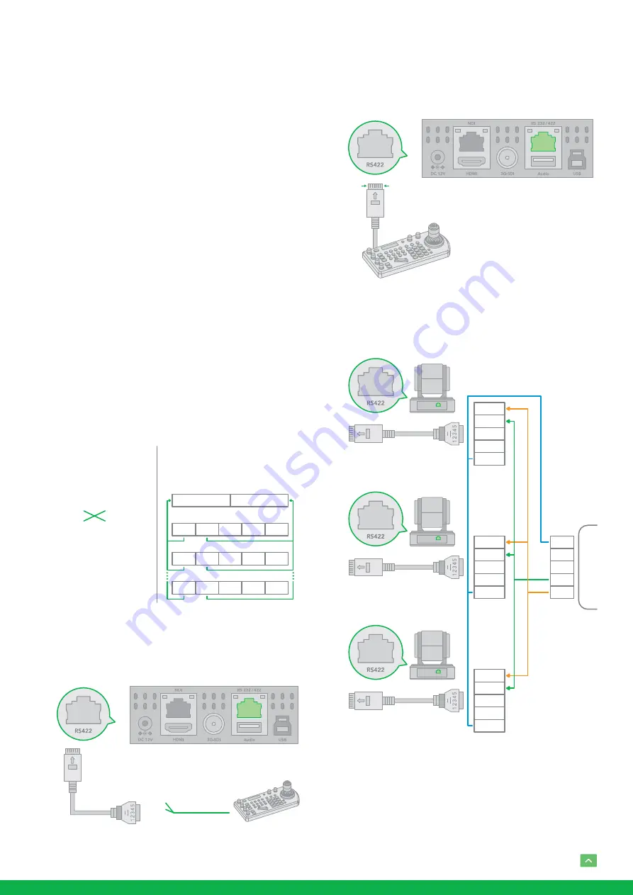
PELCO P/D Keyboard RS485 Connection
NOTE: Use RS422 ports for RS485 connection. Only use
TX+ and TX- for RS485 connection.
•
Set RS422 control method on Bottom Dip Switch.
•
Set Baud Rate on Bottom Dip Switch to the same as Baud
Rate setting on the keyboard you are using.
•
Set the camera ID on OSD menu by remote controller
•
Reboot the camera by turning it Off/On after the Bottom
Dip Switch has been set up correctly.
•
Use PELCO P/D compatible keyboard.
•
Use preset 95# on the keyboard to bring up/exit camera
OSD menu.
•
Use joystick and Button “OPEN” or “CLOSE” to navigate
OSD menu.
•
To operate keyboard, please refer to the user manual of
the keyboard you are using.
PELCO RS485 Connection
•
Use extension cables included RJ45 to RS422 Phoenix
connecter adaptor to make RS485 connection for your
control device.
Camera
1. TXD IN –
2. TXD IN +
Keyboard
6. RS485 +
7. RS485 –
RS422 (VISCA) Daisy Chain
Multiple Cameras Connection
(VISCA Keyboard)
RS485
PELCO P/D Keyboard
Connection
RX +
RX –
TX +
TX –
GND
RX +
RX –
TX +
TX –
GND
RX +
RX –
TX +
TX –
GND
1. TDX IN –2
. TDX IN +
CAM 1
KEYBOARD
CAM 2
CAM 255
Multicore
Control
Cable
PTZ Keyboard
RS485 Serial Port
connection on
controller side
VCC-CC45RS
Extension cable RS422
adaptor included
5. R –
4. R +
3. T –
2. T +
1. GND
•
Or you can use CAT5/6 T-568B Standard Ethernet cable
direct connect between the camera and the controller to
make RS485 connection by following the pin definition
below:
•
How to make RS485 multiple cameras connection with
RS485 standard serial port controller:
NOTE: For RS-232 VISCA control, this unit supports daisy
chain connection for using multiple cameras.
For control details, refer to Operating Instructions of control
keyboard/station software.
•
You need to match the communication speed (Baud Rate)
CAT5/6
Network Cable
RS485
Port
1. RX –
(Orange/White)
2. RX +
(Orange)
3. GND
(Green/White)
4. ---
(Blue)
5. ---
(Blue/White)
6. ---
(Green)
7. TX –
(Brown/White)
8. TX +
(Brown)
1
8
5. R –
4. R +
3. T –
2. T +
1. GND
VCC-CC45RS
RJ45 TO RS422/485
CONTROL CABLE ADAPTOR
5. R –
4. R +
3. T –
2. T +
1. GND
VCC-CC45RS
RJ45 TO RS422/485
CONTROL CABLE ADAPTOR
5. R –
4. R +
3. T –
2. T +
1. GND
VCC-CC45RS
RJ45 TO RS422/485
CONTROL CABLE ADAPTOR
RX +
RX –
TX +
TX –
GND
RS422
RS422 SERIAL PO
RT
ON CONTROLLER SIDE


