background image


54 


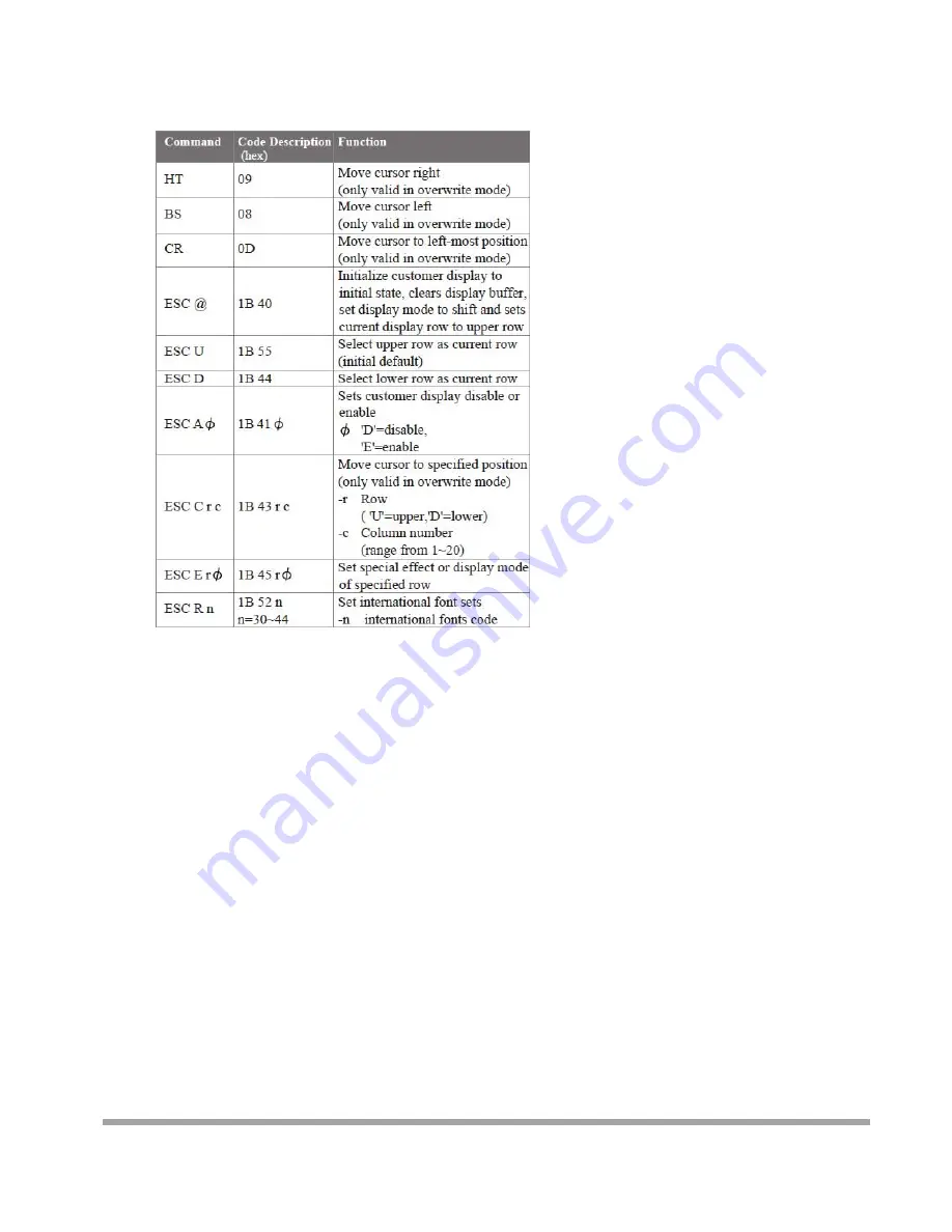
Mode 5: ICD 2002 mode 


REMARK)

* Using command "ESC E r 

Φ

", the value of parameter: 

r 58= all rows 

55= upper row 

44= lower row 

Φ

special function, the value is one of 

30= shift mode (default) 

31= rotation mode 

32= blink mode 

33= clear this row and switch to shift mode 

34= overwrite mode 

35= vertical mode


Summary of Contents for Carisma IT7000III

Page 1: ...r for incidental or consequential damages in connection with the furnishing performance or use of this material This document contains proprietary information that is protected by copy right All right...

Page 2: ...memory up to 256MB LCD Panel IT7000 15 Panel Size 15 Maximum Resolution 1024 x 768 Brightness 250 cd m1 Contrast Ratio 600 1 Response Time 8 ms View Angles H V 160 160 Touch Panel Five Wires Resistive...

Page 3: ...LAN Orange Optional Peripherals Magnetic Card Reader ISO Track 1 2 3 USB interface VFD customer display 20 x 2 characters RS 232 interface Dimensions IT 7000 15 358 W X 367 L X 173 H mm IT 7000 12 293...

Page 4: ...rton Remove the unit by carefully holding the foam inserts and remove slowly to protect the system The following items should be found in the carton 1 CD that including all driver and manual 2 The Sys...

Page 5: ...er is always on after the adapter is plugged in It may cause permanent damage to your system when you open any part of it Front View Side USB Power HDD LAN Power Button Rear View Slot for installing M...

Page 6: ...ening any part of the system Since the standby power is always on after the adapter is plugged in It may cause permanent damage to your system when you open any part of it As illustrated in the follow...

Page 7: ...onversion cables are provided in the package Please notice that the Printer and VGA connectors in the second level using JST PHD pitch 1 25 type connectors The package includes a Printer Port adapter...

Page 8: ...the system Installing Peripherals To install the peripheral s cables please follow the method described below It will make the process much easier 1 Turn the system upside down and Open the cable cov...

Page 9: ...ng The jumper you can select COM3 to COM4 9 with 5V or 12V power The second jumper is Clean CMOS 1 Release the four screws in the front panel 2 Sometime if the CPU front panel is too tight it is easie...

Page 10: ...9 Jumper JP1 COM4 JP2 COM3 Type onboard 3 x 2 pin header JP1 JP2 Mode 5 6 Standard COM Port 3 4 Pin9 with 12V signal 1 2 Pin9 with 5V signal Default setting JP2 JP1 CMOS...

Page 11: ...10 Jumper JRTC Type Onboard 3 pin jumper Normal Operation Mode 1 2 Clear CMOS 2 3 Normal Operation Default setting After changing RAM module please lock the four screws for front housing 1...

Page 12: ...11 Mount CARiSMA on Wall 1 Turn the system upside down 2 Release metal foot 3 Release the screw 4 Lock the Wall mount by screw 5 It is the same procedure to lock right side wall mount...

Page 13: ...ark the signal 6 Drill the hole on the wall 9 Lock the CARiSMA by screw Attention Please check the screw is lower than metal foot 7 Lock the metal foot on the wall 8 Insert the machine down from Upper...

Page 14: ...13 Installing Magnetic Card Reader MSR 1 Turn the system upside down 2 Open the cover of MSR cable 3 Connect the cable to MSR 4 Lock the screw to mount MSR...

Page 15: ...14 Installing Customer Display 1 Release Four screw on the back of VFD module 2 Release Two screw...

Page 16: ...15 3 Release the screws on the VFD module 4 Release the VFD board 5 Turn the system upside down 6 Open the VFD cover by fingernail...

Page 17: ...dle of the lower hinge mount hole 8 Pass the signal line through the middle of the upper of hinge mount hole 10 Pass the signal line through the middle of the VFD base 11 Connect the signal line with...

Page 18: ...17 13 Close the VFD cover Attention Make sure latches are securely 15 Install hinge cover 16 Lock the hinge cover by screw 14 Lock the VFD cover with VFD base 12 Lock the VFD board by screws...

Page 19: ...18 17 Lock the VFD module with hinge mount...

Page 20: ...hard disk cover Since the standby power is always on after the adapter is plugged in It may cause permanent damage to your system when you open any part of the system 1 Release these two screws of th...

Page 21: ...20 Installing RAM 1 Release the four screws in the front housing 2 Sometime if the CPU front panel is too tight it is easier to use a tweezers as a hook to pull the panel out...

Page 22: ...21 3 After changing RAM module please lock the four screws for front housing...

Page 23: ...peration press DEL key many times after power on beep sound to enter BIOS setup mode then press F10 and Enter It will set BIOS to default value Or connect a monitor to the second VGA port and enter BI...

Page 24: ...u to load the BIOS default values i e factory settings for fail safe system operations Load Optimized Defaults Use this menu to load the BIOS default values i e factory settings for optimal performanc...

Page 25: ...driver e TouchKit Touch Screen driver Please always install the Intel Chipset driver first and restart the Windows system before processing other driver s installation Chipset Driver Installation Ins...

Page 26: ...25 A Click the Next button on the Welcome window B Click the Yes button on the License Agreement window C Click the Next button to continue D Click the Finish button...

Page 27: ...26 VGA Driver Installation Select the CD directory to VGA...

Page 28: ...27 A Click the Next button on the Welcome window B Click the Yes button on the License Agreement window C Click the Next button to continue D Click the Finish button...

Page 29: ...28 LAN Driver Installation Select the CD directory to LAN A Click the Next button on the Welcome window...

Page 30: ...29 B Click the Finish button...

Page 31: ...30 Audio Driver Installation Select the CD directory to Step 4 Install Realtek AC97 codec Driver A Click NEXT...

Page 32: ...31 B Click the Finish button...

Page 33: ...rectory to TouchKit Driver A Double click SETUP on the My computer window B Click the Next button on the Welcome window C Click Next button on the Select Type window D Select None and Click Next E Cli...

Page 34: ...33 A Double click SETUP on the my computer window B Click the Next button on the Welcome window G Install successful and restart your system...

Page 35: ...ouch screen Always perform the Four Points Calibration of the TouchKit program after your first installation of the touch screen driver A Select Tools then 4 Points Calibration B Press the Green Blink...

Page 36: ...35 DirectX 9 Installation...

Page 37: ...any part of the system Since the standby power is always on after the adapter is plugged in It may cause permanent damage to your system when you open any part of the system Installing Peripherals Con...

Page 38: ...37 Solder side...

Page 39: ...GND 8 GND 9 GND 10 N C Connector CN_COM1 Type DF13 10 pin pitch 1 25mm Pin Description Pin Description 1 MDCD1 2 MSIN1 3 MS01 4 MDTR1 5 GND 6 MDSR1 7 MRTS1 8 MCTS1 9 12V 10 N C Connector CN_COM2 Type...

Page 40: ...r JVLCD Type 6 pin Power select Header Pin Description 1 2 LCDVCC 3 3V 3 4 LCDVCC 5V 5 6 LCDVCC 12V Connector CN_LVDS Type onboard 40 pin connector for LVDS connector Connector model HIROSE DF13 40DP...

Page 41: ...ATX3 31 BCLK 34 GND 33 GND 36 DDCPCLK 35 N C 38 DDCPDATA 37 N C 40 N C 39 N C Connector CN_JFRNT Type DF13 10 pin pitch 1 25mm Pin Description Pin Description 1 PWRBT 2 PWRBT 3 LANLED 4 LANLED 5 HDLED...

Page 42: ...NIT 7 PRD2 8 SLIN 9 PRD3 10 GND 11 PRD4 12 GND 13 PRD5 14 GND 15 PRD6 16 GND 17 PRD7 18 GND 19 ACK 20 GND 21 BUSY 22 GND 23 PE 24 GND 25 SLCT Connector CN_CRT Type DF14 25 pin pitch 1 25mm Pin Descrip...

Page 43: ...42 Character Font Table A Control code set B U S A font set 8...

Page 44: ...43 C International character selection ASCII CODE 3DH Standard Europe international font set...

Page 45: ...44 3EH Multingual international font set 3FH Portuguese international font set...

Page 46: ...45 40H Canadian French international font set 41H NORDIC internatinal font set...

Page 47: ...46 42H RUSSIA font set 43H SLAVONIC Font set...

Page 48: ...ont set System Commands Command Format Command List A Set Baud Rate COMMAND B COMPUTER EOT SOH B BAUD RATE N ETB ASCII 04H 01H 42H 31H 37H 4EH 17H Byte 1 1 1 1 1 1 DISPLAY ACK or NACK if failed ASCII...

Page 49: ...I 04H 01H 49H 30H 44H 17H Byte 1 1 1 1 1 DISPLAY ACK or NACK if failed ASCII 06H 15H Byte 1 1 Note International Character Code C Save the current view message Save Demo view data COMMAND S COMPUTER E...

Page 50: ...17H Byte 1 1 1 1 1 DISPLAY ACK or NACK if failed ASCII 06H 15H Byte 1 1 Note Some part of the current view messages can be cleared by this COMMAND It can start clearing between position 1 and position...

Page 51: ...2 select 33H means display the message with Mode 1 Mode 2 For this Demo display function you must have saved the message by COMMAND S previously For example select 37H for displaying layers and selec...

Page 52: ...he display according to the standard RS 232C communication protocols and the SOFTWARE CONTROL information listed on this chapter Command Modes The command modes can be selected with the Demo Software...

Page 53: ...52 Mode 1 EPSON Esc POS mode...

Page 54: ...53 Mode 2 UTC Standard mode Mode 3 UTC enhanced mode Mode 4 AEDEX mode...

Page 55: ...nd ESC E r the value of parameter r 58 all rows 55 upper row 44 lower row special function the value is one of 30 shift mode default 31 rotation mode 32 blink mode 33 clear this row and switch to shif...

Page 56: ...55 Mode 6 CD 5220 standard mode...

Page 57: ...56 Mode 7 DSP 800 mode Mode 8 ADM 787 788 mode...

Page 58: ...t collection recycling and disposal of electric and electronic devices and their components The crossed dustbin symbol on the device means that it should not be disposed of with other household wastes...

Reviews: