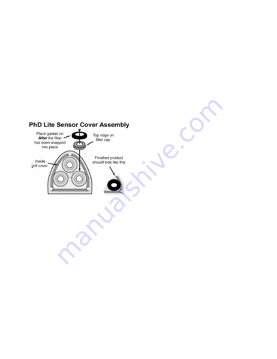
background image


56

appears, contact Biosystems Instrument Service 
Dept. for further guidance. 


PhD Lite programming includes safeguards to recognize 
maladjusted sensors.  If the settings on the new sensor 
are significantly different from those of the sensor that is 
being replaced, a message indicating that the sensor is 
reading “Too Low” or “Too High” for Auto-Calibration 
may follow the first attempt at one-button calibration. 


Note:  The first fresh air calibration adjustment after 
installation of a new sensor should be done using 
the “manual” calibration procedure as discussed in 
section 4.5 of this manual


Once the new sensor has been fresh-air calibrated 
using the “manual” calibration procedure, subsequent 
fresh air and span calibrations can be made by using 
the MODE button and One-Button Auto-Calibration 
procedures. 


6.1.2 New 

sensor 

releases 


Biosystems occasionally releases a new type of toxic 
sensor, or makes changes to existing sensors in order 
to improve performance.  In some cases it may be 
necessary to update the PhD Lite’s internal software 
before making use of the new sensor.  If a sensor that is 
incompatible with the current configuration of the 
instrument’s internal software is installed, a message 
stating that the sensor is “Not Supported” will be 
displayed at the time the instrument is turned on. 


For instructions on updating the internal instrument 
software in your PhD Lite, see section 6.4 below. 


6.1.3 Troubleshooting 

sensor 

problems 


Many difficulties with sensors can be resolved easily.  
Below are a few of the most common sensor-related 
problems.   


6.1.3.1  Can’t make automatic fresh air/zero 
calibration adjustment 


Possible causes and solutions 


1.  The atmosphere in which the instrument is located 

is contaminated (or was contaminated at the time 
the instrument was last fresh air calibrated. 


2.  A new sensor has just been installed. 


3.  Instrument has been dropped or banged since last 

turned on. 


4.  There has been a significant change in temperature 

or humidity since the instrument was last used. 


Solution: 


Take the instrument to fresh air and allow readings to 
stabilize.  Perform a manual fresh air/zero adjustment 
as discussed in section 4.5.1.  If the manual fresh 
air/zero procedure fails to correct the problem, call 
Biosystems Instrument Service Department at (860) 
344-1079 or (800) 711-6776. 

6.1.3.2  Can’t make span calibration adjustment. 


Causes: 


1.  Instrument failed the last fresh air / zero calibration. 


2.  Empty calibration gas cylinder. 


3.  Expired calibration gas cylinder. 


4.  Calibration gas setting does not correspond to 

calibration gas. 


5.  Sensor has drifted outside of the range for 

automatic calibration. 


6.  LEL only: Type of calibration gas (standard) has 

changed significantly. 


7. Dead 

sensor. 


8. Instrument 

problem. 


Solutions: 


1.  Verify that the instrument can be fresh air / zero 

calibrated by performing the procedure discussed 

above in section 6.1.3.1. 

2.  Verify that the calibration gas is not empty. 
3.  Verify that the calibration gas is not expired. 
4.  Verify that the calibration gas is the correct type for 

the sensor and that the calibration gas settings are 
identical to those given on the cylinders.  See 
section 4.7.2. for instructions related to calibration 

gas settings. 

5.  Span calibrate the instrument manually by following 

the instructions given in section 4.5.2. 

6.  If the calibration gas standard has changed 

significantly, span calibrate the instrument manually 

be following the instructions given in section 4.5.2. 

7. Replace 

sensor. 

8.  Send instrument back to Biosystems. 


6.2 Motorized 

pump 


A motorized sample pump is available for the PhD Lite 
for remote sampling.  The motorized pump is powered 
by the PhD Lite battery.  When the pump is attached 

Summary of Contents for PhD Lite

Page 1: ...Reference Manual PhD Lite Multi Gas Detector 651 South Main Street Middletown CT 06457 USA 800 711 6776 860 344 1079 Fax 860 344 1068 http www biosystems com Version 4 11 p n 13 088 19APR2007...

Page 2: ...1...

Page 3: ...ENTIALLY DANGEROUS ATMOSPHERIC CONDITIONS IT IS ESSENTIAL THAT THE INSTRUCTIONS IN THIS REFERENCE MANUAL BE READ FULLY UNDERSTOOD AND FOLLOWED PhD Lite Reference Manual Version 4 11 Copyright 2007 by...

Page 4: ...2 1 Operational warnings and cautions 11 2 2 On and off sequences 11 2 2 1 Start up sequence 11 2 2 1 1 Other start up screens 12 2 2 1 1 1 Non standard alarms 12 2 2 1 1 2 Warning Sensor Needs Cal 1...

Page 5: ...3 Adjust warning alarm levels 25 3 2 6 4 The warning alarm timeout function 25 3 2 6 4 1 Adjust timeout interval 25 3 2 6 4 2 Disabling the timeout interval 26 3 3 The Calibration Menu 26 3 4 The Opt...

Page 6: ...en sulfide 38 4 3 2 Cl2 and ClO2 Non Specific sensors 38 4 3 2 1 Cl2 Non Specific 38 4 3 2 2 ClO2 Non Specific 38 4 4 Automatic calibration 39 4 4 1 Automatic fresh air zero calibration sequence 39 4...

Page 7: ...mple probe assembly 59 6 3 1 Changing sample probe filters 59 6 3 2 Changing sample probe tubes 59 6 4 Firmware upgrade from the Biosystems website 60 6 5 Returning your PhD Lite to Biosystems for ser...

Page 8: ...d immediately An instrument that fails calibration may not be used until testing with known concentration test gas determines that accuracy has been restored and the instrument is once again fit for u...

Page 9: ...ic sensors currently available for use in the PhD Lite include hydrogen sulfide H2S carbon monoxide CO sulfur dioxide SO2 phosphine PH3 ammonia NH3 chlorine Cl2 chlorine dioxide ClO2 hydrogen cyanide...

Page 10: ...message LEL OVERRANGE will intermittently appear both the audible alarm and the flashing LED alarms will be activated and an X will appear on the LCD in the place of the numeric reading for the LEL s...

Page 11: ...lled the instrument is capable of displaying readings for up to four different channels of detection O2 LEL CO and H2S The sensor configuration of the PhD Lite can be specified at the time of purchase...

Page 12: ...ne units the battery compartment cover provides access to the set of three AA alkaline batteries The cover is held in by a knurled retention screw 9 Bottom surface The belt clip attaches to the bottom...

Page 13: ...testing with known concentration test gas determines that accuracy has been restored and the instrument is once again fit for use 7 Do not reset the calibration gas concentration unless you are using...

Page 14: ...any time Sensor ranges for individual PhD Lite sensors are given in Appendix C The procedure for changing alarm settings is discussed in section 3 2 2 Calibration Due in 30 Days After the self test an...

Page 15: ...en see below Basic Peak Mode Gas level concentrations always displayed Access to calibration functions 3 screens available scroll by pressing the MODE button 1 Current gas readings screen see below 2...

Page 16: ...arm latch see section 3 2 3 1 In Basic mode the information screen is also available to the user While in Basic mode the MODE button may be used to toggle back and forth between the current gas level...

Page 17: ...for 15 minutes For the first 15 minutes after start up the TWA screen will show an X in place of the calculation After 15 minutes the TWA calculation will be shown Appendix A discusses Permissible Exp...

Page 18: ...intrinsic safety 2 4 2 NiMH rechargeable battery The PhD Lite may be equipped with a rechargeable NiMH nickel metal hydride battery that is designed to provide up to 17 hours of continuous use betwee...

Page 19: ...atteries or Eveready L91 size AA 1 5V Lithium batteries not CSA or ATEX approved Substitution of batteries may impair intrinsic safety 2 5 Methods of sampling The PhD Lite may be used to sample the im...

Page 20: ...may lead to water ingress and may cause damage to the PhD Lite The pressure sensor in the sample draw pump is designed to detect pressure changes while the sample draw probe is being held in a vertic...

Page 21: ...m the PhD Lite The audible and visual alarms will be activated and the LCD will display the message Pump Disconnect Press the MODE button to acknowledge the disconnection and resume normal diffusion o...

Page 22: ...important information about itself to the instrument allows for a number of important PhD Lite operating benefits 2 6 1 Identification of type of sensor by instrument Sensors installed in the PhD Lit...

Page 23: ...The PhD Lite will automatically recognize the changes that have been made upon turn on and display the Warning Needs Cal message 10 Calibrate the PhD Lite with calibration gas appropriate for the new...

Page 24: ...alarms are self resetting unless the alarm latch is enabled With the alarm latch disabled visible and audible alarms cease when gas readings drop back below the pre set alarm levels With the alarm la...

Page 25: ...s will then be shown ALARM LATCH SETTINGS ALARM LATCH DISABLED 3 Once the alarm latch setting is shown the up and down navigation arrows may be used to toggle between ENABLED and DISABLED ALARM LATCH...

Page 26: ...EXIT DEF HIGH ALARM LEL 10 EXIT 4 Press the MODE button at any time to exit Set Def Alarms YES NO CANCEL 5 Press the MODE button with YES highlighted to restore default alarms The instrument will then...

Page 27: ...new warning alarm setting 3 2 6 3 Adjust warning alarm levels 1 Enter the warning alarm subdirectory of the Alarm Menu as described above in section 3 2 6 1 Use the navigation arrows to highlight ADJU...

Page 28: ...Mode selection should be based on how much information is required the skill level of the user and the nature of the job 3 4 2 1 Overview of user modes Text Only Mode Displays OK for gas level concen...

Page 29: ...c Mode It is possible to initiate the automatic calibration functions in order to make fresh air and span calibration adjustments Calibration procedures are discussed in detail in Chapter 4 3 4 2 4 1...

Page 30: ...YES NO CANCEL 4 Press the MODE button with YES highlighted to save the new operating mode Note Changing modes or otherwise reprogramming the instrument is reserved for authorized employees 3 4 3 Secu...

Page 31: ...highlighted to save the new setting 3 4 4 2 Changing the passcode To change the passcode 1 Enter the passcode subdirectory of the Options Menu as discussed in section 3 4 4 CHANGE_PASSCODE PASSCODE_ON...

Page 32: ...5 Press the MODE button with YES highlighted to save the new language settings Langue Enregistree 3 4 6 DECIMAL Changing the precision of the toxic sensor readout Toxic gas readings may be given in f...

Page 33: ...1 Use the navigation arrows to highlight CONTRAST CONTRAST BACKLIGHT ORIENTATION EXIT 2 Press the MODE button Contrast Adjust or EXIT 3 Adjust the contrast with the up and down navigation arrows When...

Page 34: ...AST BACKLIGHT ORIENTATION EXIT 2 Press the MODE button Press the up or down arrow to rotate the display or to Flip Display EXIT 3 Press the MODE button when finished Save Changes YES NO CANCEL 4 Press...

Page 35: ...1 Enter the View Menu as discussed above in section 3 6 1 Use the navigation arrows to highlight SERVICE ALARM_LEVELS BAT_VOLTAGE SERVICE VERSION EXIT 2 Press the MODE button The service information s...

Page 36: ...bove in section 3 7 1 Use the navigation arrows to highlight SERV_DATE TIME DATE SERV_DATE EXIT 2 Press the MODE button The following screen will then be shown CHANGE_SERV_DATE SERVICE_ON OFF EXIT 3 7...

Page 37: ...hlight the day month or year that requires adjustment NEXT LEL SERVICE NEXT 28 OCT 2003 EXIT NEXT LEL SERVICE NEXT 28 OCT 2003 EXIT 5 Use the up and down navigation arrows to change the setting NEXT L...

Page 38: ...gas can lead to inaccurate and potentially dangerous readings Biosystems offers calibration kits and long lasting cylinders of test gas specifically developed for easy PhD Lite calibration Use of non...

Page 39: ...rm Make sure that the PhD Lite is located in fresh air before turning the instrument back on after a combustible sensor alarm latch condition has occurred Fresh air calibration adjustments may only be...

Page 40: ...ue set to H2S Note The procedure for changing the calibration gas value setting for the CO Plus sensor is covered below in section 4 7 2 2 4 3 1 2 1 Relative response of the CO Plus sensor to carbon m...

Page 41: ...nstrument will then proceed to the following screen and begin a 5 second countdown Zero Calibration Mode Adjust 5 5 To initiate the fresh air zero calibration press the MODE button before the unit fin...

Page 42: ...prior to completion of the calibration the calibration procedure will be cancelled and the instrument will return to normal operation Wait at least 3 minutes after turning the instrument on to allow s...

Page 43: ...cedure 4 5 1 Manual fresh air calibration procedure In some cases it will be necessary to manually fresh air calibrate the PhD Lite Manual fresh air calibrations are performed as follows 1 Turn the in...

Page 44: ...inaccurate and potentially dangerous readings Span Cal CO 48 EXIT 8 Once the readings stabilize use the up and down navigation arrows to raise or lower the readings to match the level of the gas conce...

Page 45: ...to highlight MENU and press the MODE button The Main Menu will then be displayed ALARMS CALIBRATION OPTIONS SCREEN VIEW TIME EXIT 5 Use the navigation arrows to highlight CALIBRATION and press the MO...

Page 46: ...igation arrow once to highlight LEL or CH4 CALIBRATION GAS LEL 50 0 EXIT or CALIBRATION GAS CH4 2 50 EXIT 4 The up and down navigation arrows may be used to toggle between the calibration gas settings...

Page 47: ...NO CANCEL 8 Press the MODE button with YES highlighted to save the new settings Cal Gas Values Saved Do not use multi component calibration gas mixtures containing both carbon monoxide and hydrogen s...

Page 48: ...DE button 4 7 3 2 Disabling the calibration reminder To disable the calibration reminder follow the directions given in section 4 7 3 1 and decrease the interval to zero days Remind Cal Every day EXIT...

Page 49: ...ink System is a data management system that downloads instrument readings calibration information and other data from Biosystems gas detectors and automatically stores them in a user specified databas...

Page 50: ...er can be upgraded to a full user configurable datalogger at any time Call Biosystems Technical Service Department at 800 711 6776 x 509 for details 5 3 Datalogger upgrade The full datalogger option i...

Page 51: ...ruments equipped with datalogging capability will have an additional subdirectory in the Main Menu called DATALOGGER The Datalogger Menu provides access to all user configurable datalogging options To...

Page 52: ...ighlight exit and press the MODE button The following two screens will be shown in succession Longest Session Estimate 97h22m Save Changes YES NO CANCEL 6 Press the MODE button with YES highlighted to...

Page 53: ...ODE button with YES highlighted to enter communication mode and enable the IrDA port Note If an IrDA link with a PC is not established within 30 seconds of the initiation of Communications Mode the Ph...

Page 54: ...igation arrow once to highlight EXIT NEXT User 4 EXIT 13 Press the MODE button with EXIT highlighted to leave the user or location list The save changes screen will then be displayed Save Changes YES...

Page 55: ...with the instrument through the Touch ID function in the Datalogger Menu To program a Touch ID button 1 Enter a name or location into the session memory as detailed in section 5 4 5 1 2 Enter the Dat...

Page 56: ...r a Touch ID button 1 Enter the Touch ID Menu as described above in section 5 4 1 LOCATION_MEMORY USER_ID_MEMORY CLEAR_MEMORY EXIT 2 Use the up navigation arrow to highlight CLEAR ID BUTTON and press...

Page 57: ...surface of the sensor cover push out yellow dust cap with a blunt tool 3b Remove sensor blank from the sensor compartment For Sensors O2 LEL CO CO Plus CO H H2S NO DUO TOX perform step 4a then procee...

Page 58: ...s contaminated at the time the instrument was last fresh air calibrated 2 A new sensor has just been installed 3 Instrument has been dropped or banged since last turned on 4 There has been a significa...

Page 59: ...andard accessories with every 54 26 0101 motorized pump include a package of 10 replacement filters for the pump Biosystems part number 61 001 6 2 1 Pump performance The PhD Lite automatically verifie...

Page 60: ...he sample probe 6 2 2 Internal pump filter replacement The following procedure describes how to replace the internal pump filter Figure 6 2 2 Internal PhD Lite pump diagram 1 Remove the four bottom sc...

Page 61: ...ny remaining particulate contaminants Sample probe filters should be replaced whenever visibly discolored due to contamination A spare filter replacement kit Biosystems part number 54 05 K0401 is incl...

Page 62: ...rization number prior to shipment A Biosystems Instrument Service Representative will record all relevant information or special instructions at that time To ensure safe transport whenever possible pl...

Page 63: ...ay 6 05 1123 Polycarbonite Fiber Washer 7 05 1118 Screw For Display 8 10 331 Side Grip 9 10 334 Upper Alkaline Battery housing 10 10 335 Lower Alkaline Battery housing 11 35 0240 35 0241 Alkaline Main...

Page 64: ...sport oxygen Although very high concentrations of carbon monoxide may be acutely toxic and lead to immediate respiratory arrest or death it is the long term physiological effects due to chronic exposu...

Page 65: ...Sulfur dioxide 0 25 PPM 0 1 PPM 54 25 04 NH3 Ammonia For software versions prior to 2 0 0 50 PPM 1 PPM 54 25 21 NH3 Ammonia 0 100 PPM 1 PPM 54 25 08 Cl2 Chlorine non specific 0 50 PPM 0 1 PPM 54 25 18...

Page 66: ...d n d n d Hydrogen Sulfide H2S 0 5 100 20 2 20 20 60 0 2 0 0 0 n d n d Sulfur Dioxide SO2 1 1 100 1 100 50 150 0 2 n d n d 0 Nitrogen Dioxide NO2 5 8 1 0 100 90 270 0 n d n d 0 n d n d Chlorine Cl2 n...

Page 67: ...closely follow these guidelines If your operating procedures do not permit daily checking of the sensors Biosystems recommends the following procedure to establish a safe and prudent accuracy check s...

Page 68: ...ears from date of purchase Toxi Limited 2 years after activation or 2 years after the Must Be Activated By date whichever comes first Toxi3Ltd 3 years after activation or 3 years after the Must Be Act...

Reviews: