background image

TPower I45 BIOS M anual 


40 

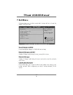
7 Exit Menu 

T his menu allows you to load the optimal default settings, and save or discard the 
changes to the BIOS items. 
 

BIOS SETU P U TILITY

Main

Advan ced

PCIPnP

Boot

Chipset

O.N.E

vxx .xx (C)Copyright 1985-200x, American Me gatrends, Inc.

S elect Screen
S elect Item
G o to Sub Screen
G eneral Help
S ave and Exit
E xit

Enter
F1
F10
ESC

Exit system setup
after saving the
changes.

F10 key can be used
for this operation.

Exit Options

Security Setti ngs

Save Changes a nd Exit

Discard Change s and Exit
Discard Change s

Load Optimal D efaults

CMOS Backup Fu nction

> Security

Exit


Save Changes and Exit 

Save all configuration changes to CMOS RAM and exit setup. 

Discard Changes and  Exit 

Abandon all changes made during the current session and exit setup. 

Discard Changes 

Abandon all changes made during the current session and restore the previously 
saved values. 

Load Optimal Defaults 

T his selection allows you to reload the BIOS when problem occurs during system 
booting sequence. T hese con figurations are  facto ry settings optimized fo r this 
system. 

Summary of Contents for TPower I45

Page 1: ...TPower I45 BIOS Manual i BIOS Setup 1 1 Main Menu 3 2Advanced Menu 8 3 PCIPnP Menu 19 4 Boot Menu 22 5 Chipset Menu 25 6 O N EMenu 29 7 Exit Menu 40 ...

Page 2: ...word protection or chipset fine tuning options are also included in BIOS The rest of this manual will to guide you through the options and settings in BIOS Setup Plug and Play Support ThisAMI BIOS supports the Plug and Play Version 1 0A specification EPA Green PC Support ThisAMI BIOS supports Version 1 03 of the EPA Green PC specification APM Support This AMI BIOS supports Version 1 1 1 2 of the A...

Page 3: ...you can use these keys to select item and change the settings Notice z The default BIOS settings apply for most conditions to ensure optimum performance of the motherboard If the system becomes unstable after changing any settings please load the default settings to ensure system s compatibility and stability Use Load Setup Default under the Exit Menu z For better system perf ormance the BIOS firm...

Page 4: ...ield Use or to configure system Time System Overview AMI BIOS System Memory 00 00 System Date Tue 01 01 2008 Floppy A SATA Configuration Version 01 01 01 Build Date 01 01 08 Size System Time 00 Exit AMI BIOS Shows systeminformation including BIOS version built date etc System Memory Shows systemmemory size VGA shard memory will be excluded System Time Set the systeminternal clock System Date Set t...

Page 5: ...SATA 5 Device SATA 6 Device Hot Plug Disabled Hard Disk Write Protect Disabled IDE Detect Time Out Sec 35 SATA 2 Configuration Enhanced Max Ports on SATA 1 6 Ports SATA 1 Configuration Compatible AHCI Configuration Options Disabled Compatible Enhanced SATA 1 Configuration Thisitem allows you to control the onboard SATAcontroller Options Compatible Default Disabled Enhanced Configure SATA 1 as This...

Page 6: ...porting AHCI BIOS Support ThisBIOS feature controls the AHCI function of the SATA controller Options Enabled Default Diabled AHCI CD DVD Boot Time Out ThisBIOS feature allows you to set the AHCI CD DVD boot time out Options 35 Default 0 5 10 15 20 25 30 AHCI Port0 Port1 Port2 Port3 Port4 Port5 BIOS SETUP UTILITY Main vxx xx C Copyright 1985 200x American Megatrends Inc Select Screen Select Item Ch...

Page 7: ... and Exit Exit F1 F10 ESC Select the type of device connected to the system Primary IDE Master LBA Large Mode Auto Block Multi Sector Transfer Auto PIO Mode Auto DMA Mode Auto S M A R T Auto 32Bit Data Transfer Enabled Device Type Auto The BIOS detects the information and values of respective devices and these information and values are shown below to the name of the sub menu Type Select the type ...

Page 8: ...able or disable 32 bit data transfer Options Enabled Default Disabled Hot Plug Thisitem allows you to control the hot plug function under RAID or AHCI mode Options Disabled Default Enabled Hard Disk Write Protect Disable or enable device write protection This will be effective only if the device is accessed through BIOS Options Disabled Default Enabled IDE Detect Time Out Sec Select the time out v...

Page 9: ...uperIO Configuration Hardware Health Configuration Smart Fan Configuration PM ACPI Configuration CPU Configuration Exit CPU Configuration Thisitem shows the CPU information that the BIOS automatically detects BIOS SETUP UTILITY Advanced vxx xx C Copyright 1985 200x American Megatrends Inc Select Screen Select Item Change Option General Help Save and Exit Exit F1 F10 ESC This should be enabled in o...

Page 10: ...processor requests for a 64 byte cache line This reduces cache latency by making the next cache line immediately available if the processor requires it as well Options Enabled Default Disabled Max CPUID Value Limit When the computer is booted up the operating system executes the CPUID instruction to identify the processor and its capabilities Before it can do so it must first query the processor t...

Page 11: ...ESC Allows BIOS to Enable or Disable Floppy Controller Configure Super IO Chipset Onboard Floppy Controller Enabled Serial Port1 Address 3F8 IRQ4 Keyboard PowerOn Disabled Mouse PowerOn Disabled Restore on AC Power Loss by IO Power Off Onboard Floppy Controller Select enabled if your system has a floppy disk controller FDC installed on the system board and you wish to use it If you installed anoth...

Page 12: ...Options Power Off Default Power ON LastState Hardware Health Configuration Thisitem shows the system temperature fan speed and voltage information Advanced Hardware Health Configuration H W Health Function Enabled Shutdown Temperature Disabled CPU Temperature SYS Temperature CPU Fan Speed JSFAN1 Speed JNFAN1 Speed CPU Voltage NB SB Voltage 3 30V 3 3VSB VBAT 12 0V DDR2 Voltage FSB Voltage BIOS SETU...

Page 13: ...ntrol Smart Fan Configuration CPU Smart Fan Disabled JSFAN1 Smart Fan Disabled JNFAN1 Smart Fan Disabled Smart Fan Calibration Fan Ctrl OFF C o Fan Ctrl On C Fan Ctrl Full On C JSFAN1 Start Speed RPM JSFAN1 Max Speed RPM Auto detect Max FAN Speed Fan Ctrl OFF C Fan Ctrl On C Fan Ctrl Full On C o o o o o JNFAN1 Start Speed RPM JNFAN1 Max Speed RPM Auto detect Max FAN Speed CPU Smart Fan Thisitem al...

Page 14: ...lue Options 0 127 Fan Ctrl Full On If the SystemTemperature reaches the set value FAN willrun in full speed Options 0 127 JSFAN1 JNFAN1 Start Speed RPM Thisitem allows you to set the start speed of the FAN Options 1000 3000 JSFAN1 JNFAN1 Max Speed RPM Thisitem allows you to set the max speed of the FAN Options 1000 3000 Auto Detect Max FAN Speed Thisitem will help you find out the max workable spe...

Page 15: ...res ACPI v1 0 ACPI APIC support Enabled AMI OEMB table Enabled Headless mode Disabled RTC Alarm Enable Disable APIC ACPI SCI IRQ APIC ACPI SCI IRQ Options Disabled Default Enabled USB Dev ice Wakeup from S3 S4 Thisitem allows you to enable or disabled the USB resume from S3 S4 function Options Disabled Default Enabled High Performance Event Timer Thisitem allows you to enable or disabled the HPET ...

Page 16: ...oot up until it goes to the operating system before this function will work Active State Power Management This item sets the ASPM configuration for the PCI Express devices before the operating system boots This f unction is for OS which does not support ASPM Options Disabled Default Enabled Suspend mode The item allows you to select the suspend type under the ACPI operating system Options S1 POS D...

Page 17: ...s without a keyboard monitor or mouse To run in headless mode both BIOS and operating system e g WindowsServer 2003 must supportheadless operation Options Disabled Default Enabled USB Configuration Thisitem shows the USB controller and using USB device information BIOS SETUP UTILITY Advanced vxx xx C Copyright 1985 200x American Megatrends Inc Select Screen Select Item Change Option General Help S...

Page 18: ... 1 1 12Mbps BIOS EHCI Hand Off This item allows you to enable support for operating systems without an EHCI hand off feature Options Enabled Default Disabled USB Mass Storage Dev ice Configuration BIOS SETUP UTILITY Advanced vxx xx C Copyright 1985 200x American Megatrends Inc Select Screen Select Item Change Option General Help Save and Exit Exit F1 F10 ESC Number of seconds POST waits for the US...

Page 19: ...ESC Onboard PCI PC I E Devices Configu ration Onboard PCIE P ATA SATA Cntlr D isabled Onboard PCIE G iga LAN A uto Onboard LAN Bo ot ROM D isabled MAC ID Informa tion Options Disabled Enabled Onboard PCIE PATA SATA Cntlr Thisitem allows you to control the onboard PATA SATAcontroller Options Disabled Default Enabled Onboard PCIE Giga LAN Thisitem allows you to control the onboard LAN Options Auto D...

Page 20: ... Boot Advanced PCI P nP Settings WARNING Setti ng wrong values in below sections may c ause system to malf unction Plug Play O S No PCI Latency Ti mer 64 Allocate IRQ t o PCI VGA Yes Palette Snoopi ng Dis abled PCI IDE BusMas ter Ena bled OffBoard PCI I SA IDE Card Aut o IRQ3 Ava ilable IRQ4 Ava ilable IRQ5 Ava ilable IRQ7 Ava ilable IRQ9 Ava ilable Clear NVRAM No Exit Clear NVRAM Thisitem allows ...

Page 21: ...ace Options Disabled Default Enabled PCI IDE BusMaster Thisitem is a toggle for the built in driver that allows the onboard IDE controller to perform DMA Direct Memory Access transfers Options Enabled Default Disabled OffBoard PCI ISA IDE Card Thisitem is for any other non onboard PCI ISA IDE controller adapter Options Auto Default Disabled IRQ3 4 5 7 9 10 11 14 15 These items will allow you to as...

Page 22: ...TPower I45 BIOS Manual 21 Reserved Memory Size Thisitem allows BIOS to reserve certain memory size for specific PCI device Options Disabled Default 16K 32K 64K ...

Page 23: ...Boot vxx xx C Copyright 1985 200x American Me gatrends Inc S elect Screen S elect Item C hange Option G eneral Help S ave and Exit E xit F1 F10 ESC Allows BIOS to skip certain tests while booting This will decrease the time needed to boot the system Boot Settings Configuration Full screen lo go display En abled AddOn ROM Disp lay Mode Fo rce BIOS Bootup Num Loc k On PS 2 Mouse Sup port Au to Wait ...

Page 24: ...IRQ12 for the PS 2 mouse or allow other devices to make use of this IRQ Options Auto Default Enabled Wait for F1 If Error This BIOS feature controls the system s response when an error is detected during the boot sequence Options Enabled Default Disabled Hit DEL Message Display ThisBIOS feature allows you to control the display of the Hit DEL to enter Setup message during memory initialization Opt...

Page 25: ...You can also change the booting sequence The number of device items that appears on the screen depends on the number of devices installed in the system Removable Drives The BIOS will attempt to arrange the removable drive boot sequence automatically You can also change the booting sequence The number of device items that appears on the screen depends on the number of devices installed in the syste...

Page 26: ... setting inappropriate values in items of this menu may cause system tomalfunction BIOS SETU P U TILITY Main Advan ced PCIPnP Boot Chipset O N E vxx xx C Copyright 1985 200x American Me gatrends Inc S elect Screen S elect Item G o to Sub Screen G eneral Help S ave and Exit E xit Enter F1 F10 ESC Advanced Chips et Settings WARNING Setti ng wrong values in below sections may c ause system to malf un...

Page 27: ...ical memory DISABLE Do not allow remapping of memory Memory Remap Feature This item allows you to enable or disable the remapping of the overlapped PCI memory above the total physical memory Only 64 bit OS supports this function Options Enabled Default Disabled Memory Hole You can reserve this area of system memory for ISA adapter ROM When this area is reserved it cannot be cached Check the user i...

Page 28: ... Ports 4 USB Ports 6 USB Ports 8 USB Ports 10 USB Ports 12 USB Ports USB Functions The item determines the number of functional USB port Options 12 USB Ports Default 10 USB Ports 8 USB Ports 6 USB Ports 4 USB Ports 2 USB Ports Disabled USB Port Configuration Options 6X6 USB Ports Default USB 2 0 Controller Thisentry is to enabled disabled EHCI controller only This Bios itself may may not have high...

Page 29: ...TPower I45 BIOS Manual 28 SMBUS Controller ThisBIOS feature controls the I O buffers for the SMBus Options Enabled Default Disabled SLP_S4 Min Assertion Width Options 4 to 5 seconds Default ...

Page 30: ...al OverClock Sys tem Over Clocking Navigator N ormal Memory Test D isabled Auto OverClock System V 6 Tech Engine Intel R Speed Step tm tech E nabled Ratio CMOS Set ting x9 0 CPU Frequency Setting 3 33 Over Clock Ret ry Count 3 FSB Bsel To N orthBridge Latch A uto FSB Compensati on FineTune D isabled DRAM Frequency A uto DDR2 Enhanced Mode A uto DRAM Timing Configuration Clock Gen Configuration CPU...

Page 31: ...et ting x9 0 CPU Frequency Setting 3 33 Over Clock Ret ry Count 3 FSB Bsel To N orthBridge Latch A uto FSB Compensati on FineTune D isabled DRAM Frequency A uto DDR2 Enhanced Mode A uto DRAM Timing Configuration Clock Gen Configuration CPU Configur ation Voltage Conf iguration Exit Options Normal Automate OverClock Manual OverClock The Overclock Navigator provides 3 different engines helping you t...

Page 32: ...e Conf iguration Memory Test D isabled Auto OverClock System V 6 Tech Engine Exit Options Normal Automate OverClock Manual OverClock MOS is designed for experienced overclock users It allows users to customize personal overclock setting Intel R SpeedStep tm Tech This item allows you to enable SpeedStep technology for better power saving SpeedStep is a technology built into some Intel processors th...

Page 33: ...DR2 ram enhanced mode Options Auto Default Enabled Disabled DRAM Timing Configuration BIOS SETU P U TILITY O N E vxx xx C Copyright 1985 200x American Me gatrends Inc S elect Screen S elect Item C hange Option G eneral Help S ave and Exit E xit F1 F10 ESC DRAM Timing Co nfiguration DDR2 RCOMP Con figuration A uto Config Static tREAD V alue PL A uto Configure DRAM Timing by SPD E nabled DRAM tCL 5 ...

Page 34: ...uto Default 1T 15T Configure DRAM Timing by SPD Options Enabled Default Disabled DRAM tCL Options 5 Default DRAM tRP Options 5 Default DRAM tRCD Options 5 Default DRAM tRAS Options 15 Default DRAM tWR Options 6 Default DRAM tRFC Options 42 Default DRAM tWTR Options 3 Default DRAM tRRD Options 3 Default ...

Page 35: ... Options 5 Default PrechargeAll to Act Delay Options 5 Default PrechargeAll Refresh Delay Options 5 Default R to W Delay Options 8 Default R to R Delay Same Rank Options 4 Default W to W Delay Same Rank Options 4 Default W to R Delay Same Rank Options 11 Default Refresh Counter Options Auto Default 2600T 3120T 4171T 5200T ...

Page 36: ...ws BIOS to Select PCI E Over Clock Note MIN 100 Mhz MAX 150 Mhz PCIE Frequency Setting Thisitem allows you to select the PCIE clock control Options 100 Default Min 100 Max 150 CPU Clock Skew Control Thisitem allows you to select the CPU clock skew Options Auto Default 100ps 1500ps with an interval of 100ps G MCH Clock Skew Control Thisitem allows you to select the northbridge clock skew Options Au...

Page 37: ... Support C1E is Enhanced Halt State function this f unction helps to save power and decrease heat by lowering CPU frequency while the processor is not working Options Enabled Default Disabled CPU TM Function The CPU TM Function is to throttle the clock speed of higher speed Prescott s to help keep them cool Options Enabled Default Disabled Intel R C State Tech This item allows you to control the C...

Page 38: ...H GTL Ref vo ltage A uto CPU PLL Voltag e 1 5 V CPU Voltage NB SB Voltage DDR2 Voltage FSB Voltage CPU Voltage Control CPU Voltage Thisitem allows you to select CPU Voltage Control Options Auto Default 0 050V 1 300V DDR Voltage Thisitem allows you to select DDR Voltage Control Options Auto Default 0 050V 1 850V Chipset Voltage Thisitem allows you to select NB SB Voltage Control Options Auto Defaul...

Page 39: ... Manual 38 CPU Core2 GTL Ref Voltage Options 0 67 VTT Default 0 69 VTT 0 63 VTT 0 61 VTT MCH GTL Ref Voltage Options Auto Default 0 61 VTT 0 64 VTT 0 59 VTT 0 56 VTT CPU PLL Voltage Options 1 5V Default 1 6V 1 7V 1 8V ...

Page 40: ...uto DDR2 Enhanced Mode A uto DRAM Timing Configuration Clock Gen Configuration CPU Configur ation Voltage Conf iguration Memory Test E nabled Exit Options Disabled Enabled Step 2 When the process is done change the setting back from Enabled to Disabled to complete the test BIOS SETU P U TILITY Main Advan ced PCIPnP Boot Chipset O N E vxx xx C Copyright 1985 200x American Me gatrends Inc S elect Sc...

Page 41: ...operation Exit Options Security Setti ngs Save Changes a nd Exit Discard Change s and Exit Discard Change s Load Optimal D efaults CMOS Backup Fu nction Security Exit Save Changes and Exit Save all configuration changes to CMOS RAM and exit setup Discard Changes and Exit Abandon all changes made during the current session and exit setup Discard Changes Abandon all changes made during the current s...

Page 42: ...Boot Sector Vi rus Protection Dis abled Exit Change SupervisorPassword Setting the supervisor password will prohibit everyone except the supervisor from making changes using the CMOS Setup Utility You will be prompted with to enter a password User Acess Level Thisitem allows supervisor to set the user level Options Full Access Default No Access View Only Limited Change User Password If the Supervi...

Page 43: ...ttings into BIOS ROM and reload any saved CMOS setting for customizing system configurations Moreover users are able to save an ideal overclock setting during overclock operation There are 10 sets of record addresses in total and users are able to name the CMOS data according to personal preference BIOS SETU P U TILITY Main Advan ced PCIPnP Boot Chipset O N E vxx xx C Copyright 1985 200x American ...

Reviews: