14 |
Chapter 2: Hardware installation
2.6 Jumper & Switch Setting
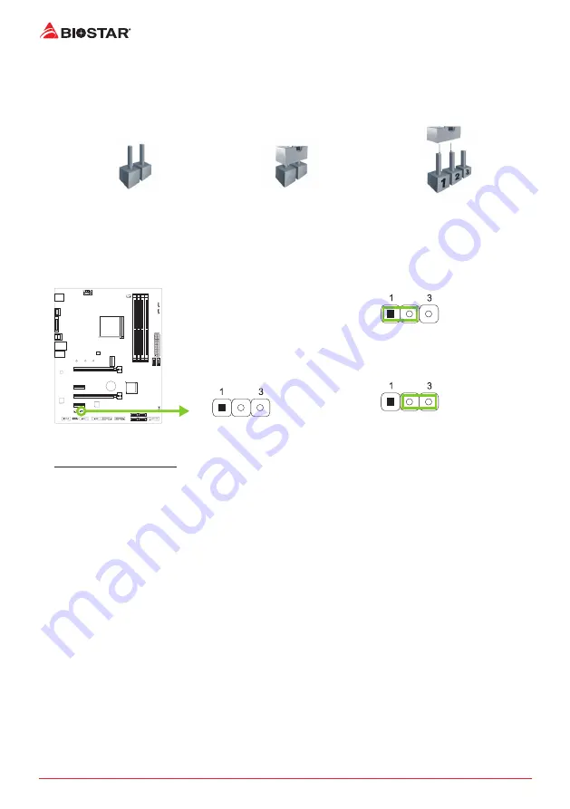
The illustration shows how to set up jumpers. When the jumper cap is placed on pins, the
jumper is “close”, if not, that means the jumper is “open”.
Pin opened
Pin closed
Pin 1-2 closed
JCMOS1: Clear CMOS Jumper
The jumper allows users to restore the BIOS safe setting and the CMOS data. Please carefully
follow the procedures to avoid damaging the motherboard.
Pin 1-2 Close:
Normal Operation (default).
Pin 2-3 Close:
Clear CMOS data.
Clear CMOS Procedures:
1. Remove AC power line.
2. Set the jumper to “Pin 2-3 close”.
3. Wait for five seconds.
4. Set the jumper to “Pin 1-2 close”.
5. Power on the AC.
6. Load Optimal Defaults and save settings in CMOS.
Summary of Contents for Racing X570GTA
Page 6: ...6 Chapter 1 Introduction 1 5 Motherboard Layout Note represents the 1st pin...
Page 45: ...FCC FCC 15 Class B BIOSTAR BIOSTAR BIOSTAR CE 2004 108 CE 2006 95 CE 1999 05 CE...
Page 47: ...3 X570GTA 1 1 0 45 1 2 Serial ATA x4 ATX I O x1 x1 x1...
Page 50: ...6 1 5 1...
Page 51: ...7 X570GTA 2 1 CPU 1 CPU 2 90 3 CPU CPU...
Page 52: ...8 4 CPU CPU 2 2 A 1 2...
Page 53: ...9 X570GTA B 1 2 CPU CPU CPU CPU...
Page 68: ...24 UEFI BIOS RACING GT EVO Utility RACING GT EVO RACING GT EVO 1 2 3 4...
Page 70: ...26 UEFI BIOS GT Touch Windows RACING GT EVO ECO 1 2 3...
Page 72: ...28 UEFI BIOS LED LED LED LED LED LED 9 VIVID LED DJ LED LED...
Page 74: ...30 UEFI BIOS 1 CPU 2 3 CPU...
Page 75: ...UEFI BIOS 31 X570GTA 1 2 3 Default 4 5 6 CPU CPU...
Page 76: ...32 UEFI BIOS Racing GT EVO Utility...
Page 81: ...37 X570GTA 4 5 RAID RAID Block 2 6 8 Uses RAID 0 RAID 1 2 RAID 1 RAID1 RAID 2 2 RAID 1 100 2...


