

50-RN61PAM2S-Q-B1
The information in this document is subject to change without notice and does not represent a commitment on part of the vendor, who assumes no liability
or responsibility for any errors that may appear in this manual.
No warranty or representation, either expressed or implied, is made with respect to the quality, accuracy or fitness for any particular part of this document.
In no event shall the manufacturer be liable for direct, indirect, special, incidental or consequential damages arising from any defect or error in this manual
or product.
Product names appearing in this manual are for identification purpose only and trademarks and product names or brand names appearing in this docu-
ment are the property of their respective owners.
This document contains materials protected under International Copyright Laws. All rights reserved. No part of this manual may be reproduced, transmit-
ted or transcribed without the expressed written permission of the manufacturer and authors of this manual.
If you do not properly set the motherboard settings, causing the motherboard to malfunction or fail, we cannot guarantee any responsibility.
Copyright and Warranty Notice
Q: How to get a quick response for my request on technical support?
A: Please carry out a simple troubleshooting before sending “Technical Support Form” on our website.
Q: Is the motherboard dead? Do I need to return it to where I bought from or go through an RMA
process?
A: After you had gone through the troubleshooting procedures, yet the problem still exists, or you find an
evident damage on the motherboard. Please contact your reseller shop to get the RMA service.
Serial NO. Definition
Q&A of Technical Support
Package Checklist
▲ Installation Guide x 1
▲ HDD Cable x 1
▲ Fully Setup Driver CD x 1
▲ Rear I/O Panel x 1
(full version manual files inside)
▲ Serial ATA Cable x 1
▲ FDD Cable x 1 (optional)
▲ Serial ATA Power Cable x 1 (optional)
▲ Parallel Printer Cable x1 (optional)
Note: The package contents may differ by area or your motherboard version.
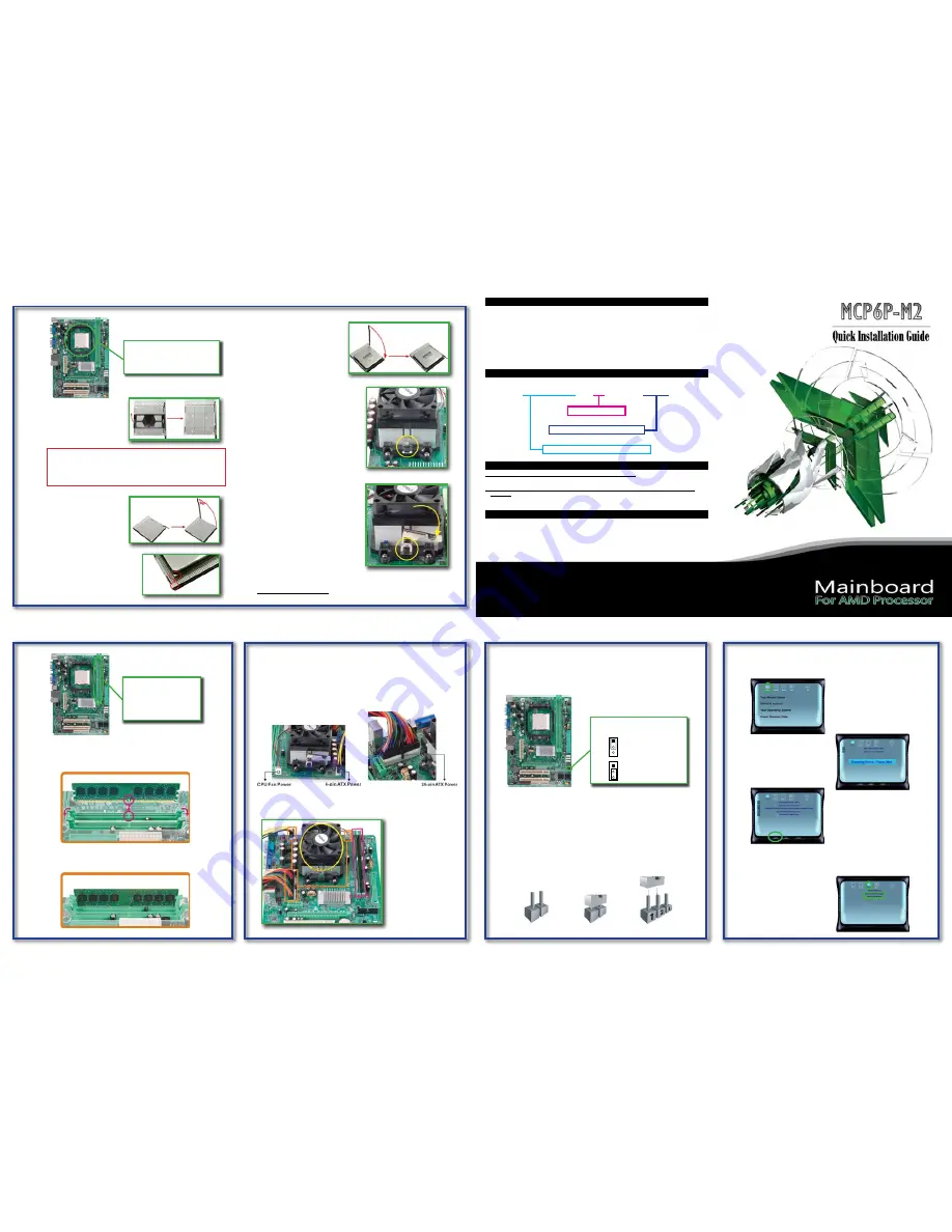
Step 1:CPU Installation
Step 1: Remove the protection cap
from the CPU socket and keep
the cap well.
Step 2: Pull the socket locking lever out
from the socket and then raise
the lever up to a 90-degree
angle.
Step 3: Look for the triangular cut edge on
socket, and the golden dot on CPU
should point forwards this triangular
cut edge. The CPU will fit only in the
correct orientation.
Step 4: Hold the CPU down firmly, and
then lower the lever to locked
the position.
AM2 CPU Socket
Supports AMD Sempron / Athlon 64 /
Athlon 64 FX / Althlon 64 X2 processor
FSB: Supports up to 1GHz Bandwidth
Step 2:Memory Installation
Step 1: Unlock a DIMM slot by pressing the retaining clips outward. Align a
DIMM on the slot such that the notch on the DIMM matches the break
on the Slot.
DDR2 DIMM Slot x2
Supports DDR2 533/667/800
Each DIMM supports 256MB /
512MB / 1GB / 2GB DDR2
Max Memory Capicity is 4GB
Step 2: Insert the DIMM vertically and firmly into the slot until the retaining chip
snap back in place and the DIMM is properly seated.
Step 3:Power Connection
The Occasion to Clear CMOS
1. Forgot the supervisor/user password preset in the BIOS menu.
2. Unable to boot up the system because the CPU clock was incorrectly set in the
BIOS menu.
3. The CMOS data becomes corrupted.
Click on
Driver
to start the process
of driver installation.
The installation program will detect
your system to find out the driver
needed to be installed.
Click on
Install
and the program
will begin to install the proper
driver for your system.
When the driver installation completes, there will be a dialogue appears asking
you to restart the system. Please click on
YES
to restart your computer.
For more information of the mainboard setup and BIOS setup, please refer to the
full version manual in the setup CD.
Clear CMOS Header
In the Setup CD auto-run program,
click on
Manual
and then click on
Mainboard User Manual
or
BIOS User Manual
.
CAUTION
Our RMA policy only accepts the mainboard comes with the cap on the
CPU socket, so please keep the protection cap well after installation. We
will not be responsible for any damage to the pin-leg of the CPU socket
resulting from misplacement/loss/incorrect removal of the protection cap.
24-pin ATX Power (JATXPWR1)
JATXPWR1 is the main power supply connector located along the edge of the
board next to the CPU socket. Firmly plug the power supply cable into the con-
nector and make sure it is secure.
Step 5: Place the heatsink and fan assembly
onto the retention frame. Match the
heatsink clip with the socket
mounting-lug. Hook the spring clip to
the mounting-lug.
Step 6: On the other side, push the retention
clip straight down to lock into the plastic
lug on the retention frame, and then
press down the locker util it stops.
Note:
Do not forget to connect the CPU fan connector. For further information, please refer
to
Step 3:Power Connection
.
CPU Fan Power (JCFAN1)
JCFAN1 supports 4-pin head connector. When connecting with wires onto con-
nectors, please note that the black wire is Ground and should be connected to
pin#1(Ground).
4-pin ATX Power (JATXPWR2)
JATXPWR2, the 4-pin ATX 12V power connection, is used to provide power to the
CPU. Align the pins to the connector and press firmly until seated.
Installation Complete
Follow the three steps to
finish CPU, memory, and
power installation, and
the whole motherboard
assembly should looks like
this picture.
Clear CMOS Header
(CMOS1)
1
3
1
3
Pin 1-2 Close:
Normal Operation
(default)
Pin 2-3 Close:
Clear CMOS data
Clear CMOS Procedure
1. Remove AC power line.
2. Set the jumper to “Pin 2-3 close”.
3. Wait for five seconds.
4. Set the jumper to “Pin 1-2 close”.
5. Power on the AC.
6. Reset your desired password or clear the CMOS data.
NOTE: How to Setup Jumpers
The illustration shows how to set up jumpers. When the jumper cap is placed on pins,
the jumper is “close”, if not, that means the jumper is “open”.
Pin Opened
Pin Closed
Pin 1-2 Closed
Driver & Manual
After you installed your operating system, please insert the Fully Setup Driver CD
into your optical drive and install the driver for better system performance.
You will see following window after you insert the CD.
N61PAM2S-xx 60xxxxxxx00001
PCB Version NO.
Serial NO. of Production
Manufacturer’s Internal Part NO.


