


M
M
M
7
7
7
V
V
V
I
I
I
Z
Z
Z
4
4
4
0
0
0
0
0
0
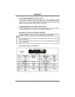
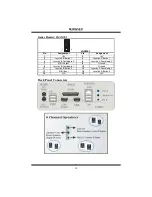
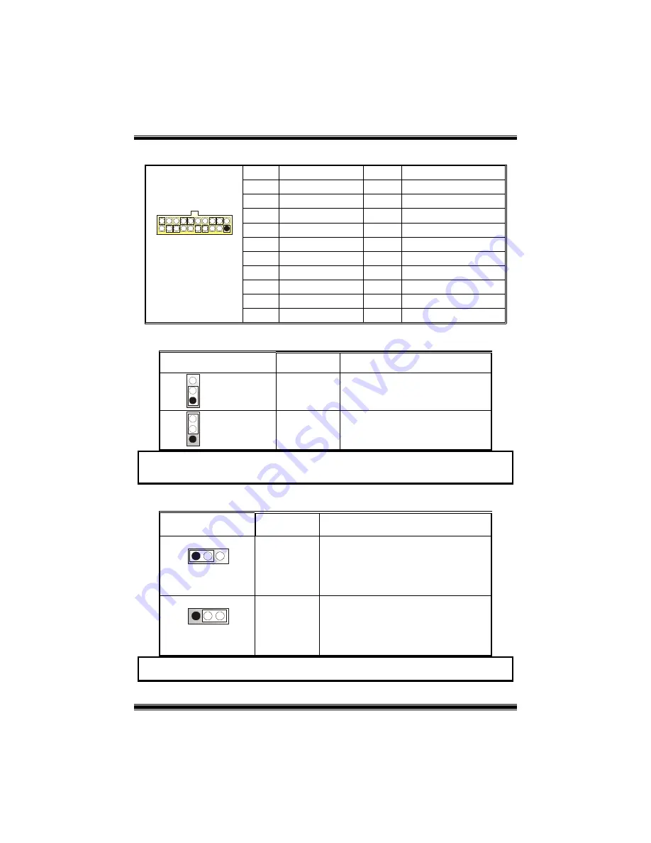
Power Connectors: JATXPWR1
PIN Assignment PIN
Assignment
1
+3.3V
11
+3.3V
2
+3.3V
12
-12V
3
Ground
13
Ground
4
+5V
14
PS_ON
5
Ground
15
Ground
6
+5V
16
Ground
7
Ground
17
Ground
8
PW_OK
18
-5V
9
Standby V5V
19
+5V
20
11
10
1
JATXPWR1
10
+12V
20
+5V
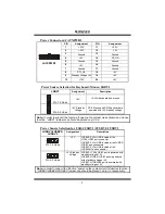
Power Source Selection for Keyboard/ Mouse: JKBV1
JKBV1
Assignment
Description
1
3
Pin 1-2 close
+5V
+5V for keyboard and mouse
1
3
Pin 2-3 close
+5V Standby
Voltage
PS/2 Mouse and PS/2 Keyboard are
powered with +5V standby voltage
Note:
In order to support the function “power-on the system via keyboard and mouse
function, “JKBV1” jumper cap should be placed on pin 2-3.
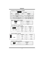
Power Source Selection for USB: JUSBV1/ JUSBV2/ JUSBV3
JUSBV1/JUSBV2/
JUSBV3
Assignment
Description
1
3
Pin 1-2 close
+5V
JUSBV3: 5V for USB located at the
J1394_USB1 port connector
JUSBV2: 5V for USB located at the JUSB2/
JUSB1 port connectors
JUSBV1: 5V for USB located at the
JUSBLAN1 port connector
1
3
Pin 2-3 close
+5V Standby
Voltage
JUSBV3: J1394_USB1 port is powered with
standby voltage of 5V
JUSBV2: JUSB2/ JUSB1 ports is powered
with standby voltage of 5V
JUSBV1: JUSBLAN1 port is powered with
standby voltage of 5V
Note:
In order to support the function “power-on the system via USB devices function,
“JUSBV1/JUSBV2/ JUSBV3” jumper cap should be placed on pin 2-3 respectively.
8


