background image

2.4

2.4

2.4

2.4

2.4    Installation and Setup

    Installation and Setup

    Installation and Setup

    Installation and Setup

    Installation and Setup

In this section, you will learn how to install the CPU, DDR Module,

In this section, you will learn how to install the CPU, DDR Module,

In this section, you will learn how to install the CPU, DDR Module,

In this section, you will learn how to install the CPU, DDR Module,

In this section, you will learn how to install the CPU, DDR Module,

and also how to set up jumpers and all the information about the components

and also how to set up jumpers and all the information about the components

and also how to set up jumpers and all the information about the components

and also how to set up jumpers and all the information about the components

and also how to set up jumpers and all the information about the components

on the motherboard. Not only can you find the installation steps, but also

on the motherboard. Not only can you find the installation steps, but also

on the motherboard. Not only can you find the installation steps, but also

on the motherboard. Not only can you find the installation steps, but also

on the motherboard. Not only can you find the installation steps, but also

the details and locations of the components on the motherboard.

the details and locations of the components on the motherboard.

the details and locations of the components on the motherboard.

the details and locations of the components on the motherboard.

the details and locations of the components on the motherboard.

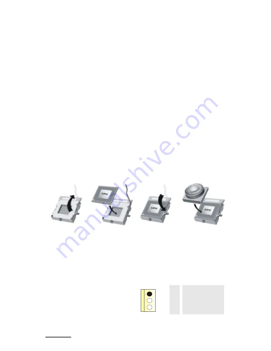
1. CPU Installation

The motherboard supports Intel Pentium 4 processor in the 478 pin package. The motherboard uses

a CPU socket called PGA478 for easy CPU installation. When you are installing the CPU, make sure the CPU has

a cooling fan attached on the right to prevent overheating. If you do not find the cooling fan, contact your dealer

and make sure to install them before turning on the computer.

Step1:

Step1:

Step1:

Step1:

Step1: Pull the lever sideways away from the socket and then raise the lever up to a 90-

degree angle.

Step2:

Step2:

Step2:

Step2:

Step2: Look for the white dot/cut edge. The white dot/cut edge should point towards the

lever pivot. The CPU will fit only in the correct orientation.

Step3:

Step3:

Step3:

Step3:

Step3: Hold the CPU down firmly, and then close the lever.
Step4: 

Step4: 

Step4: 

Step4: 

Step4: Put the CPU fan on the CPU and buckle it. Connect the CPU fan power cable to the

JCFAN1. This completes the installation.

2 Central Processing Unit: CPU

These fan headers  support cooling fans built in the computer. Orient the fans to make the heat sink

fins to allow air flow to go across the onboard heat sinks instead of the expansion slots. The fan wiring and plug

may be different according to the fan manufacturer. Connect the fan fable to the connector while matching the

black wire to the ground pin.

(1) CPU Fan Header: JCFAN1

1

 Pin

Assignment

  1

Ground

  2

+12V

  3

FAN RPM Sense

16

Summary of Contents for IDEQ 210P

Page 1: ...io or television reception which can be determined by turning the equipment off and on the user is encouraged to try to correct the interference by one or more of the following measures Reorient or relocate the receiving antenna Increase the separation between the equipment and receiver Connect the equipment into an outlet on a circuit different from that to which the receiver is connected Consult...

Page 2: ...anies Copyright Notice Copyright Notice Copyright Notice Copyright Notice Copyright Notice No part of this manual may be reproduced or transmitted in any form or by any means electronic or mechanical photocopying recording or otherwise stored in any retrieval system of any nature without the prior written permission of the manufacturer Trademark Trademark Trademark Trademark Trademark Other produc...

Page 3: ... way that people can not step on it Do not place anything over the power cord The power cord must be rated for the product and for the voltage and current marked on the product s electrical ratings label The voltage and current rating of the cord should be greater than the voltage and current rating marked on the product 11 All cautions and warnings on the equipment should be noted 12 If the equip...

Page 4: ... 25 Section 4 Software and Utilities 31 Section 4 Software and Utilities 31 Section 4 Software and Utilities 31 Section 4 Software and Utilities 31 Section 4 Software and Utilities 31 4 1 Installing Drivers and Utilities 32 Section 5 T Section 5 T Section 5 T Section 5 T Section 5 Trouble Shooting rouble Shooting rouble Shooting rouble Shooting rouble Shooting 35 35 35 35 35 5 1 System Does Not St...

Page 5: ......

Page 6: ...imple by step installation guide of the manual you will find that it is a simple by step installation guide of the manual you will find that it is a simple process to set up CPU memory and hard disk drive that takes only three process to set up CPU memory and hard disk drive that takes only three process to set up CPU memory and hard disk drive that takes only three process to set up CPU memory an...

Page 7: ...ter make sure you have enough room to set up your system Then open the package and check the following items If there are system Then open the package and check the following items If there are system Then open the package and check the following items If there are system Then open the package and check the following items If there are system Then open the package and check the following items If ...

Page 8: ...8 ...

Page 9: ......

Page 10: ...odec JPRNT1 IDE1 IDE2 J1394B1 FDD1 Super I O IT 8712 DDR2 AGP1 PCI1 JPANEL1 JOUT1 JMIC1 JUSBV1 SPDIFI1 JCDIN1 1 1 23 24 JCOM1 JCOM2D J1394A1 JRJ45USB1 JKBMS1 JAUDIO SPDIFO1 JATXPWR2 LAN 1 JUSBV3 JCMOS1 JUSB2 JUSB1 1 1 1 1 JIR1 2 1 2 25 26 1 JCL1 1 JUSBV2 1 JWOL1 1 1 JCFAN1 1 Wireless LAN Chip JUSB4 JUSB3 SATA2 SATA1 1 1 IEEE 1394 Chip Socket 754 CPU JCOM2 1 2 9 10 NVIDIA CK 8 SATA Chip JKBMSV1 1 U...

Page 11: ...o In Header C PCI1 Peripheral Component Interconnect Slot D JUSBV1 Power Source Selection for JUSB3 JUSB4 E Front Panel Connectors F JWOL1 Wake On LAN Header G SPDIFIN1 Digital Audio Connector H JUSB1 2 Front USB Headers I JUSBV3 Power Source Selection for JUSB1 JUSB2 J JPRNT1 Parallel port K J1394B1 Front 1394B Header L JATXPWR1 2 ATX Power Connector M JSFAN1 System Fan Header N JPANEL Front Pane...

Page 12: ...nd headers connectors and also the installation guide to help you a quick and headers connectors and also the installation guide to help you a quick and headers connectors and also the installation guide to help you a quick and correct installation of your system correct installation of your system correct installation of your system correct installation of your system correct installation of your...

Page 13: ...Mb s and 1000Mb s auto negotiation operation Half Full duplex capability Supports ACPI PCI power management Wireless LAN Air LinkTM optional Chip RTL8180 Full compliance with IEEE802 11 and IEEE802 11b specifications Supports Advanced Configuration Power management Interface ACPI and PCI power management system for modern operating systems Supports remote wake up in both ACPI and APM environments ...

Page 14: ... Board Peripherals a Rear side Supports 2 serial ports COM1 COM2 Supports Audio ports in vertical Supports 1 RJ 45 LAN jack Supports PS 2 mouse and PS 2 keyboard Supports USB2 0 ports Supports 1 S PDIF Out connector Supports 1 IEEE 1394A connector Supports 1 parallel port b Front Side Supports 1 floppy port supports 2 FDDs with 360K 720K 1 2M 1 44M and 2 88Mbytes Supports 1 IEEE1394A port Supports...

Page 15: ...s APM1 2 Supports ACPI Supports USB Function The setup procedures can be found in the Setup Driver CD Software Supports WarpspeederTM 9th TouchTM FLASHERTM WatchdogTM WinFlasherTM and StudioFun optional Offers the highest performance for Windows 98 SE Windows 2000 Windows Me Windows XP Linux UNIX series etc 15 ...

Page 16: ...locations of the components on the motherboard the details and locations of the components on the motherboard the details and locations of the components on the motherboard 1 CPU Installation The motherboard supports Intel Pentium 4 processor in the 478 pin package The motherboard uses a CPU socket called PGA478 for easy CPU installation When you are installing the CPU make sure the CPU has a cool...

Page 17: ...the DIMM matches the break on the slot 2 Insert the DIMM firmly and vertically into the slot until the retaining chip snap back in place and the Dimm is properly seated 4 How to set up Jumpers The illustration shows how to set up jumpers When the Jumper cap is placed on pins the jumper is close If no jumper cap is placed on the pins the jumper is open The illustration shows a 3 pin jumper whose pi...

Page 18: ...ripheral Component Interconnect and it is a bus standard for expansion cards This PCI slot is designed as 32 bits 4 Accelerated Graphics Port Slot AGP1 4 Accelerated Graphics Port Slot AGP1 4 Accelerated Graphics Port Slot AGP1 4 Accelerated Graphics Port Slot AGP1 4 Accelerated Graphics Port Slot AGP1 Your monitor will attach directly to that video card This motherboard supports video cards for P...

Page 19: ...d USB interface peripherals such as USB HDD digital cameras MP3 players printers modems etc Pin Assignment Pin Assignment 1 5V fused 2 5V fused 3 USBP4 4 USBP5 5 USBP4 6 USBP5 7 Ground 8 Ground 9 KEY 10 NC 8 Power Source Selection for USB JUSBV1 JUSBV2 JUSBV3 8 Power Source Selection for USB JUSBV1 JUSBV2 JUSBV3 8 Power Source Selection for USB JUSBV1 JUSBV2 JUSBV3 8 Power Source Selection for USB...

Page 20: ...a network 11 Case Open Connector JCL1 11 Case Open Connector JCL1 11 Case Open Connector JCL1 11 Case Open Connector JCL1 11 Case Open Connector JCL1 Pin Assignment 1 Case Open Signal 2 Ground 12 CD ROM Audio In Header JCDIN1 12 CD ROM Audio In Header JCDIN1 12 CD ROM Audio In Header JCDIN1 12 CD ROM Audio In Header JCDIN1 12 CD ROM Audio In Header JCDIN1 This header allows you to receive stereo a...

Page 21: ...Ground 17 NA 18 KEY 19 NA IrDA 20 KEY IrDA 21 5V Connector 22 Ground Connector 23 IRTX 24 IRRX 10 Power Connectors JATXPWER1 JATXPWR2 10 Power Connectors JATXPWER1 JATXPWR2 10 Power Connectors JATXPWER1 JATXPWR2 10 Power Connectors JATXPWER1 JATXPWR2 10 Power Connectors JATXPWER1 JATXPWR2 The motherboard supports ATX power supply for the power system Before installing the power supply connector pl...

Page 22: ...nel Connectors 11 Back Panel Connectors 11 Back Panel Connectors 11 Back Panel Connectors 11 Back Panel Connectors PS 2 Keyboard PS 2 Mouse Speaker Out Line In Mic In JAUDIO USB LAN IEEE 1394 SPDIFO1 COM1 COM2 22 ...

Page 23: ......

Page 24: ... parties be sure that they function As these devices are provided by third parties be sure that they function As these devices are provided by third parties be sure that they function correctly when connected to your computer before you purchase them correctly when connected to your computer before you purchase them correctly when connected to your computer before you purchase them correctly when ...

Page 25: ...t any peripherals observe the following instructions Before you connect any peripherals observe the following instructions Turn off the computer and the peripheral device Read the instructions on the manual or guide provided by the device manufacturer carefully Insert the connector that comes from the device manufacturer to the proper I O port Install the drivers or other software that s required ...

Page 26: ...connectors instead of PS 2 Before connecting mouse and keyboard make sure the connector is USB compliant or PS 2 compliant Plug the mouse cable into the black USB port if your mouse uses the PS 2 connector plug the cable into the green PS 2 port located on the rear panel of your computer Plug the keyboard cable into the black USB port if your keyboard uses the PS 2 connector plug the cable into th...

Page 27: ... symbol of USB connector facing up Insert the connector to the USB port The OS will automatically detect the device and install the driver for the device If the operating system does not have the driver for your device install the driver from the driver CD that is provided by the device manufacturer figure3 5 Note Note Note Note Note The USB devices support hot plugging eliminating the need to pow...

Page 28: ...like USB devices Match the shape of the IEEE 1394 connector to the IEEE 1394 port Insert the connector and make sure that it is connected The OS will start running and automatically install the driver for the device If the OS does not have the driver for your device install the driver from the driver CD that is provided by the device manufacturer figure3 6 Connecting Audio Equipment Your computer ...

Page 29: ...ase the cable kits However many printers are now using USB as their input connector Connecting the printer port Match the pins and the shape of the printer connector to the printer port Plug it in firmly Tighten it up with the locking screw on the connector Install the driver from the driver CD or diskette provided by the printer manufacturer Restart the computer if asked to by the OS Connecting t...

Page 30: ...t on broadband Internet connection by using the LAN port Connect your LCD PC to a network as follows The LAN jack is located on the back of your LCD PC Plug an RJ 45 network cable in the LAN jack The other end should be connected to a network hub or switch or to a peer computer 30 ...

Page 31: ......

Page 32: ...VD ROM or Combo depends on your configuration and the Installation Utility will auto run or you can launch the Driver CD Installation Utility manually Figure 4 1 There are two kinds of Installation Procedure Automatically install drivers from CD by using CD installation utility 1 Simply put Driver CD into your optical drive 2 The installation wizard will auto run and show the name of the main boar...

Page 33: ...iver you want to install 9 The utility will invoke other applications to complete the rest of installation 10 Follow the installing instructions to finish the installation 11 Click on the next driver you want to install 12 Repeat steps 8 to 10 until you have installed all the drivers the utility has for you Installing Utilities We also provide you some very useful utilities to enhance the experien...

Page 34: ...34 ...

Page 35: ......

Page 36: ... socket are OK there may be a power supply failure Contact your computer dealer for technical support and service Keyboard and power LEDs light and sound comes from the computer but the monitor remains blank Make sure the monitor is turned on and its power cable is securely plugged into a working outlet Make sure the monitor display cable is plugged securely into the back of the computer If availa...

Page 37: ...ard mouse or receiver is connected when you start the computer If you inadvertently start the system with the keyboard disconnected shut down the system by pressing and holding the power button on the system unit for at least four seconds Keyboard doesn t take input mouse pointer does not move Make sure the mouse plug is inserted in the mouse connector on your computer and the keyboard plug is ins...

Page 38: ...er Install the driver for your USB device Then plug in your USB device USB device works when first plugged in but does not work after system is woken from Standy mode Force the device to configure by unplugging and then plugging it back in Use a complete shutdown hold the power button for four seconds whenever you stop the system This forces all devices to be reconfigured the next time the system ...

Page 39: ...t the programmers did not anticipate the programmers did not anticipate the programmers did not anticipate the programmers did not anticipate the programmers did not anticipate A problem behaves erratically or refuses to accept user input Wait a while The problem might be busy processing data or waiting for some event such as network activity If possible use the task bar to switch to other problem...

Page 40: ...40 ...

Page 41: ......

Page 42: ...t Avoid transporting or using your computer in dirty or dusty environments Use a clean container when you transport the computer Avoid getting dirt and dust in the optical drive Avoid spilling liquids on the computer You can occasionally use a vacuum to clean the ports Make sure that the computer is turned off before unplugging it When you disconnect cords remember to pull them by the plugs and no...

Page 43: ... cord or plug is damaged or frayed 2 If liquid spills on the computer 3 If the LCD PC is dropped or the chassis is damaged Never push any objects of any kind into chassis openings They may touch dangerous voltage points or short parts which could result in fire or electrical shock Turn off the computer before installing or removing a peripheral device except USB or IEEE 1394 devices Turn off the c...

Page 44: ...44 ...

Page 45: ......

Page 46: ...op panels Then remove the front cover panel for inserting the mainboard into panels Then remove the front cover panel for inserting the mainboard into panels Then remove the front cover panel for inserting the mainboard into panels Then remove the front cover panel for inserting the mainboard into panels Then remove the front cover panel for inserting the mainboard into the chassis the chassis the...

Page 47: ...nsert the mainboard into the base of the chassis and place it close to the back panel After fixing the mainboard on the base of the chassis youwillfindtherearesixmountingholeof screws both on the computer chassis and the mainboard Use the screwdriver to fasten the screws Figure A 4 Figure A 5 Figure A 6 47 ...

Page 48: ...ches to JPANEL1 connector on the Mainbord Connect the cable of system fan to JSFAN1 connector on the mainboard Connect the cable to the floppy CD ROM and HDD Place the CD ROM bracket and and fix it with 2 screws Figure A 7 Figure A 8 Figure A 9 Figure A 10 48 ...

Page 49: ...it with four screws to complete the installation of mainboard Note The figures show the locations of the connectors on P4SBA motherboard Please refer to section 2 the Motherboard layout of K8NBP for the correct locations of the connectors Figure A 11 Figure A 12 Figure A 13 49 ...

Reviews: