background image

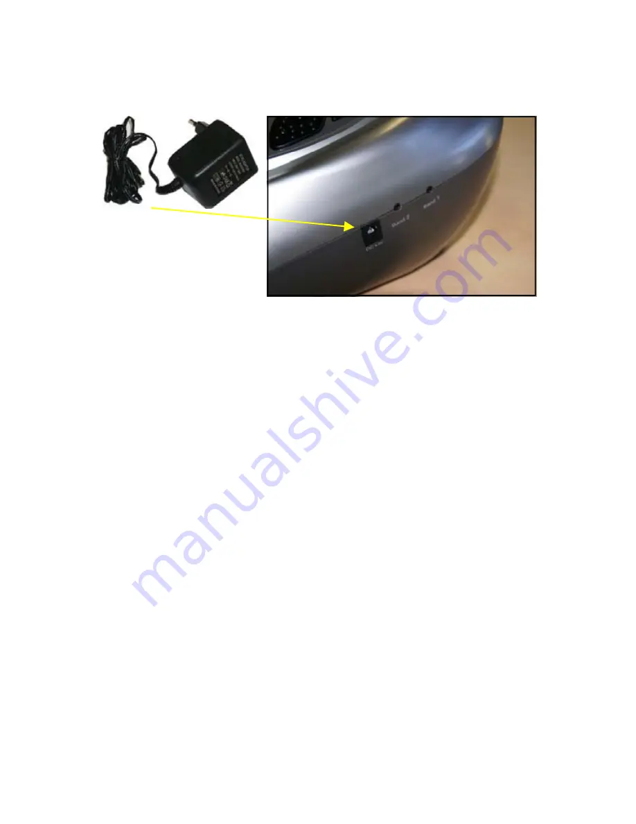
CONNECT WITH SUPPLIED POWER ADAPTER 


Plug the DC plug of  
the power supply into 
the socket on the side 
of the ElectroFlex. 
Plug in the power adaptor to a suitable wall socket.  (Make sure 
that the input voltage of the wall socket is suitable for the sup-
plied adaptor. 


INSTALLING THE BATTERIES  
 

If you want to use the ElectroFlex with battery power instead of 
the supplied main adapter, the battery compartment is located  
On the under side of the unit.  
 
Remove the battery cover from the unit. Insert three new 1.5V  
size C batteries with the + and - marks correctly aligned.  
 
Note on batteries:   
Do not mix different types of batteries or an old battery with a 
new one. To prevent the risk of leakage of explosions, never 
recharge the batteries, apply heat or take them apart.  
 
When not using batteries, remove them to prevent battery drain. 
If liquid leaks from the batteries, throw them away.  Thoroughly 
clean the battery compartment with a dry cloth. 

Summary of Contents for ElectroFlex

Page 1: ...USER MANUAL Please read before use A comfortable and relaxing micro current stimulation treatment designed to help alleviate pain and soreness associated with a variety of conditions...

Page 2: ...s a medical device This home use unit is designed for general physical conditioning No medical claims are implied or warranted 1 Long term effects of chronic electrical stimulation are unknown so plea...

Page 3: ...d reflexologist could put pressure on different reflex points or energy lines on the sole and side of the feet to deter mine the cause of illness The Benefits of Foot Reflexology 1 Reduces the level o...

Page 4: ...MACHINE OVERVIEW PART NAMES A B C D E F A Electrode silicone area for foot treatment B Far infra red light C LCD display screen D Sole massage roller E Far infra red light F Carrying handle...

Page 5: ...A intensity UP for band 1 left side 1 to 40 B intensity DOWN for band 1 left side 1 to 40 C intensity UP for band 2 right side 1 to 40 D intensity DOWN for band 2 right side 1 to 40 E program UP choo...

Page 6: ...more detail later in your instructions but the principle is relatively easy to understand There are two separate controls channels one for each foot The reason for this is that you can adjust the int...

Page 7: ...TWO prickly massage THREE combined massage FOUR pulsed prickly massage FIVE tapping massage 2 SIX fast tapping massage SEVERN fast tapping prickly massage EIGHT V fast tapping prickly massage NINE pul...

Page 8: ...n adjust the program anytime Once re adjusted the intensity will return to 0 So you will have to increase the intensity to the desired level 7 To terminate the massage period user can turn off the uni...

Page 9: ...e with a wet cloth or change for new ones replacement parts will be available directly from Bio Energiser or your distributor Don not clean the electrode gel pads with any chemical ALWAYS try and prot...

Page 10: ...ed main adapter the battery compartment is located On the under side of the unit Remove the battery cover from the unit Insert three new 1 5V size C batteries with the and marks correctly aligned Note...

Page 11: ...g locators you will need to squeeze the locator on the outside face this will push the locking locator out of it s fixed position and allow you to remove and change the roller TECHNICAL SPECIFICATION...

Page 12: ...PO Box 4359 Kidderminster DY10 4WU Tel 44 0 1562 752700 info bioenergiser com www bioenergiser com...

Reviews: