background image

Twister/Barcode Reader Interface Guide

6

Install the Barcode Reader, Continued

Step

Action

6

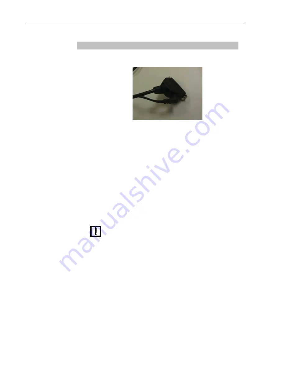
The 25-pin end of the barcode reader communications cable has a socket
for the power cable. Plug the power cable into this socket, as shown below.

7

Plug the 25-pin end of the barcode reader cable into the 25-pin end of the
adapter cable.

8

Plug the other end of the adapter cable (9-pin) into port A on the back of the
Twister. Then plug the power cable into an appropriate power source. (See
the 

Symbol LS 1220 Product Reference Manual

 for power requirements.)

9

Plug the manual trigger cable into the split cable on the back of the barcode
reader.

10

To test the reader, locate the "Set Defaults" barcode on page 6-2 of the

Symbol LS 1220 Product Reference Manual

. Hold this barcode in front of

the reader, and press the manual trigger. Hold the page far enough away
from the reader (i.e., behind the platform) so that you can scan the laser
over the barcode until you hear a "beep."

NOTE

If the test barcode does not scan, verify that
all communications cables and power cords
are securely plugged into the Twister, the
computer, the device, and the barcode reader.

11

Review the 

Symbol LS 1220 Product Reference Manual

 (included in this

interface package) for other features and functions of the barcode reader.

Summary of Contents for 400-0174

Page 1: ...P N 400 0174 Title BIO RAD LOGO B W Creator Twister Barcode Reader Interface Guide...

Page 2: ......

Page 3: ...of microplates by the external device providing increased walk away time The Twister software is designed to run under Windows 95 and Windows NT4 0 WARNING Use this product only in the manner describ...

Page 4: ...ed will result in death or serious injury WARNING A potentially hazardous situation which if not avoided could result in death or serious injury NOTE A cautionary statement operating tip or maintenanc...

Page 5: ...ual or on the product Hazardous fumes Hot surface risk of burns Ground symbol CE compliance mark Output Input Signifies that the unit has passed safety tests for grounding high voltage spikes and volt...

Page 6: ......

Page 7: ...4 PARTS LIST 4 INSTALL THE BARCODE READER 5 INSTALL THE BARCODE READER INTERFACE SOFTWARE 7 START THE TWISTER SOFTWARE 8 TEACH THE BARCODE READER POSITION 9 3 OPERATION WITH THE ULTRAMARK 11 LOADING T...

Page 8: ......

Page 9: ...screwdriver Twister Setup Required Lid Storage Platform properly installed and configured Twister software Version 2 0 or above Barcode Reader Interface software compatible with Twister software V2 0...

Page 10: ......

Page 11: ...uctions Never perform any operation on the instrument in an environment where potentially damaging liquids or gases are present Installation Notes NOTE Do not loosen tighten any screws or touch parts...

Page 12: ...d for repair use the original packing materials and shipping carton If the shipping carton has been damaged in transit it is particularly important to retain it for inspection by the carrier in case t...

Page 13: ...ction 1 Locate the mounting bracket and the four 4 screws 2 Align the four screw holes on the bottom of the barcode reader with the four holes in the mounting bracket 3 Using the four 4 screws attach...

Page 14: ...ments 9 Plug the manual trigger cable into the split cable on the back of the barcode reader 10 To test the reader locate the Set Defaults barcode on page 6 2 of the Symbol LS 1220 Product Reference M...

Page 15: ...nel Folder 4 Double click the Add Remove Programs icon to display the Add Remove Programs dialog box 5 On the Install Uninstall tab click the Install button 6 Insert disk 1 of the Barcode Reader Inter...

Page 16: ...e attempts to communicate with the Twister 3 The Twister checks all COM Ports and attempts to communicate with the Twister If an error message is displayed check that the Twister is plugged in and tur...

Page 17: ...the reader position either manually or automatically Note Manual training will result in more precise alignment of the reader and the plates To manually train the position a Hold down the manual trig...

Page 18: ...urrent settings to the plate displayed in the Plate Description textbox If the plate is the current default the Twister will be updated automatically NOTE You must now exit the Twister software and th...

Page 19: ...the Ultramark When you perform a plate run each barcode is scanned and recorded in a plate file in Microplate Manager See the Microplate Manager User Guide for details Loading the Microplates in the...

Page 20: ......

Page 21: ...Screen After the Barcode Reader Interface Kit is installed the Barcode Parameters screen is displayed when setting the run options in the interface software for the specific device The Barcode Parame...

Page 22: ...play the next screen in the Run Configuration window If barcode reading is desired Step Action 1 Click the Log Barcodes checkbox to select it The checkbox displays a check mark 2 In the Log File Path...

Page 23: ...k are protected by the plate above them Rotary Home The Twister arm s furthest position of travel in a clockwise direction Standard Capacity The standard capacity of the Twister is up to 20 microplate...

Page 24: ......

Page 25: ...Option 10 D Damage 3 I Installation Barcode Reader 4 Barcode Reader Interface Software 5 Notes 1 Warnings 1 Introduction 1 L Load the Microplates 9 Log Barcodes Checkbox 10 Log File Path Textbox 10 M...

Reviews: