15
LARGE CONTROL PANEL
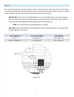
The larger FAST® control panels are provided with box-lid enclosures. The face of the enclosure features
model and serial numbers, power indicator lamp, alarm indicator lamp, alarm silence button, and blower
switch. The electrical details of the control panel are printed on a label affixed to the outside of the enclosure.
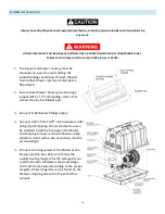
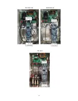
The inside of the control panel enclosure contains a printed circuit board, and a contactor and overload rated
for the blower motor horsepower, voltage, and phase.
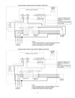
Some panels will also contain a transformer mounted next to the contactor. Terminations for incoming and
outgoing power are made in the field between the circuit board,
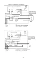
contactor and overload, and blower, based on the electrical diagram
supplied for each panel specifically.
Note:
The overload amperage setting supplied for a
given motor size is pre-set to the appropriate place at
the factory and does not need field adjustment.
If an overload trips when energized, make sure to double-check all
connections and electrical details for the control panel, blower, and
facility power supply.
The circuit board has two sets of normally open dry contacts for optional
connections such as a float switch or pressure switch. The normally
open contacts will activate the panel alarm when closed. Next to these
contacts are a 12VDC terminal that can be used to power an external
dialer device, and an alarm output terminal that can be used to signal an
external device when the panel goes into alarm. The alarm output is a
normally open switch that will close during an alarm condition
.
LARGE CONTROL PANEL
Summary of Contents for HighStrengthFAST 4.5
Page 2: ...1...
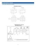
Page 15: ...12 FUJI BLOWER 1 PH FUJI BLOWER 3 PH...
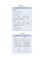
Page 16: ...13 GAST BLOWER 1 PH...
Page 19: ...16 3PH 208V 240V 1PH 208V 240V 3PH 460V...
Page 20: ...17 CONTROL PANEL SCHEMATICS...
Page 21: ...18...
Page 22: ...19...
Page 23: ...20...

