EN - 16
7 Operation
M-Drive
7 Operation
7.1 Control elements
7.1.1 Standard M-Drive
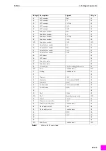
Pin
Description
Signals
X59 pin
1
Speed sensor
Vcc
a1
2
Speed sensor
Ch B
a2
3
Speed sensor
Gnd
a3
4
Speed sensor
Ch A
a4
Tab. 10
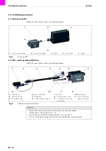
Control lead for wire actual value encoder
NOTICE
• The M-Drive wire feeder system may only be operated by qualified personnel (in Germany see
TRBS 1203).
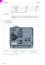
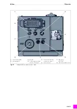
1
Reset button S9
2
Gas test S8
3
Motor control lead jack X41
4
Wire actual value encoder
control lead jack X59
5
Blast air port (AG G3/8")
6
Coolant return hose (red) connector,
nom. diam. 5
7
Coolant supply hose (blue)
connector, nom. diam. 5
8
Central socket ZL including gas
connection
Fig. 11
M-Drive control elements – central connector
1
2
3
4
5
8
7
6
Summary of Contents for 881.3112
Page 106: ...ES 28 Notas M Drive Notas ...
Page 107: ...M Drive Notas ES 29 Notas ...

