


5
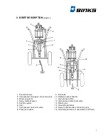
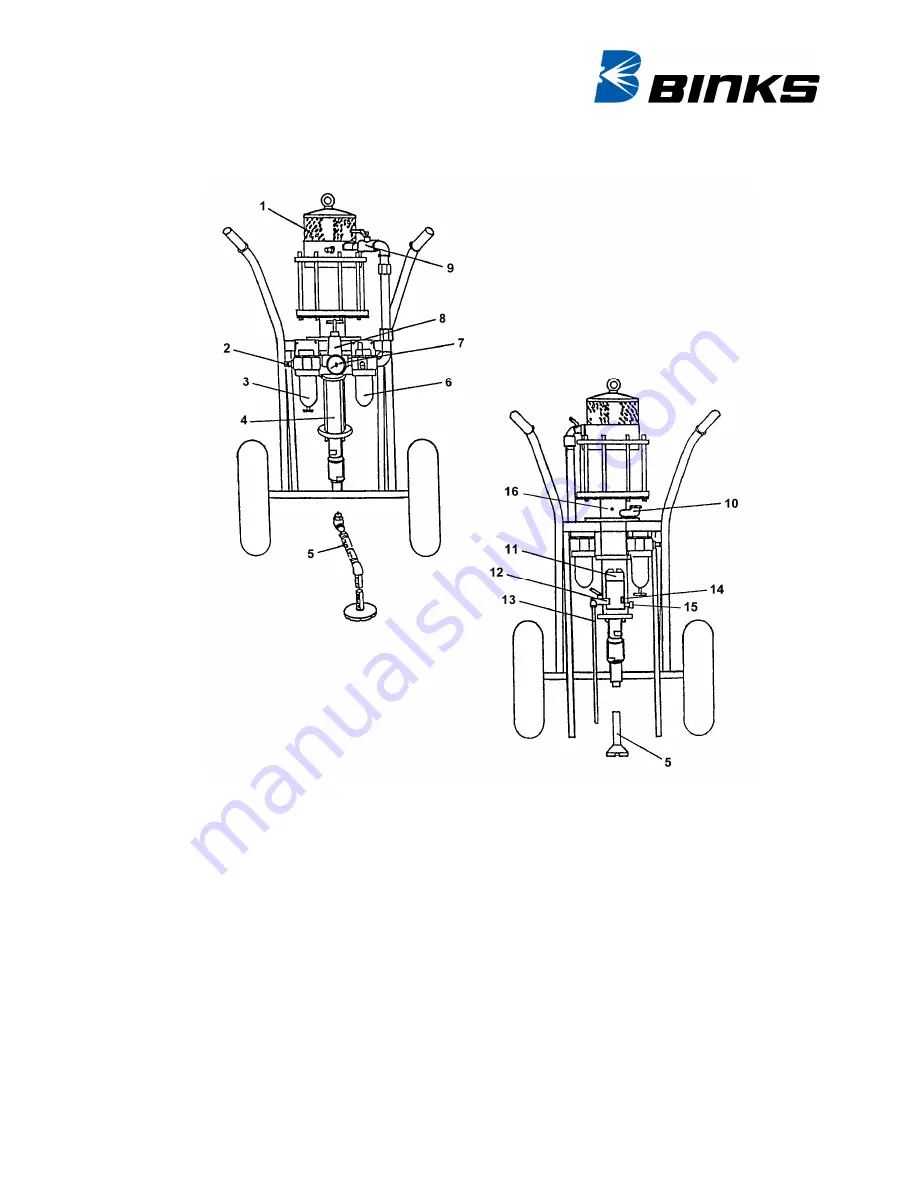
2. BRIEF DESCRIPTION
(FIGURE 1)
1 Pneumatic drive
9 Ball valve
2 Compressed air supply connection piece
10 Release agent chamber
3 Water seperator
11 High pressure filter
4 Spray material pump
12 High pressure filter relief valve
5 Suction system
13 Return pipe
6 Oiler
14 Grounding terminal
7 Compressed air control valve
15 Spray material outlet connection piece
8 Pressure reducer
16 Grounding terminal (if used without HP-filter)
Summary of Contents for HP 6/60
Page 2: ...2 ...
Page 22: ...22 TEST DOCUMENTS Test document no Date of test Expert Company Name 12 SPARE PARTS LISTS ...
Page 32: ......
Page 33: ......