© 2004 ITW Finishing Systems and Products
3
SETUP AND OPERATION
Refer to “TYPICAL INSTALLATION” drawing below
Set up the “Steadi-Grip” with the CONVENTIONAL or HVLP gun along with at least 1.5m (5 ft.) of air
and fluid hose. Attach air hose from extractor to air inlet on handle of steadigrip assembly. Pour paint
into canister with liner. Re-attach lid to canister and firmly tighten four knobs over canister lid. Set air
pressure from air regulator mounted on extractor and fluid pressure by adjusting fluid pressure
adjustment knob on cup handle.
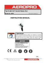
INTRODUCTION
Binks “Steadi-Grip” Pressure Cups are CE marked in accordance with the
ATEX Directive 94/9/EC, Cat 2 G X for use in Zones 1 and 2.
These Cups are ideal for component spraying and industrial applications where small batch
production spraying is required. The 2 qt. capacity is sufficient to complete large spray jobs without
refilling the cup. Its lightweight and rugged construction is excellent for portability allowing the
operator to make fluid and air control adjustments quickly and efficiently at the spray station.
NOTE
Before refilling canister with paint, shut
odd air supply to the cup and release
pressure from canister by rotating pres-
sure relief knob counter clockwise
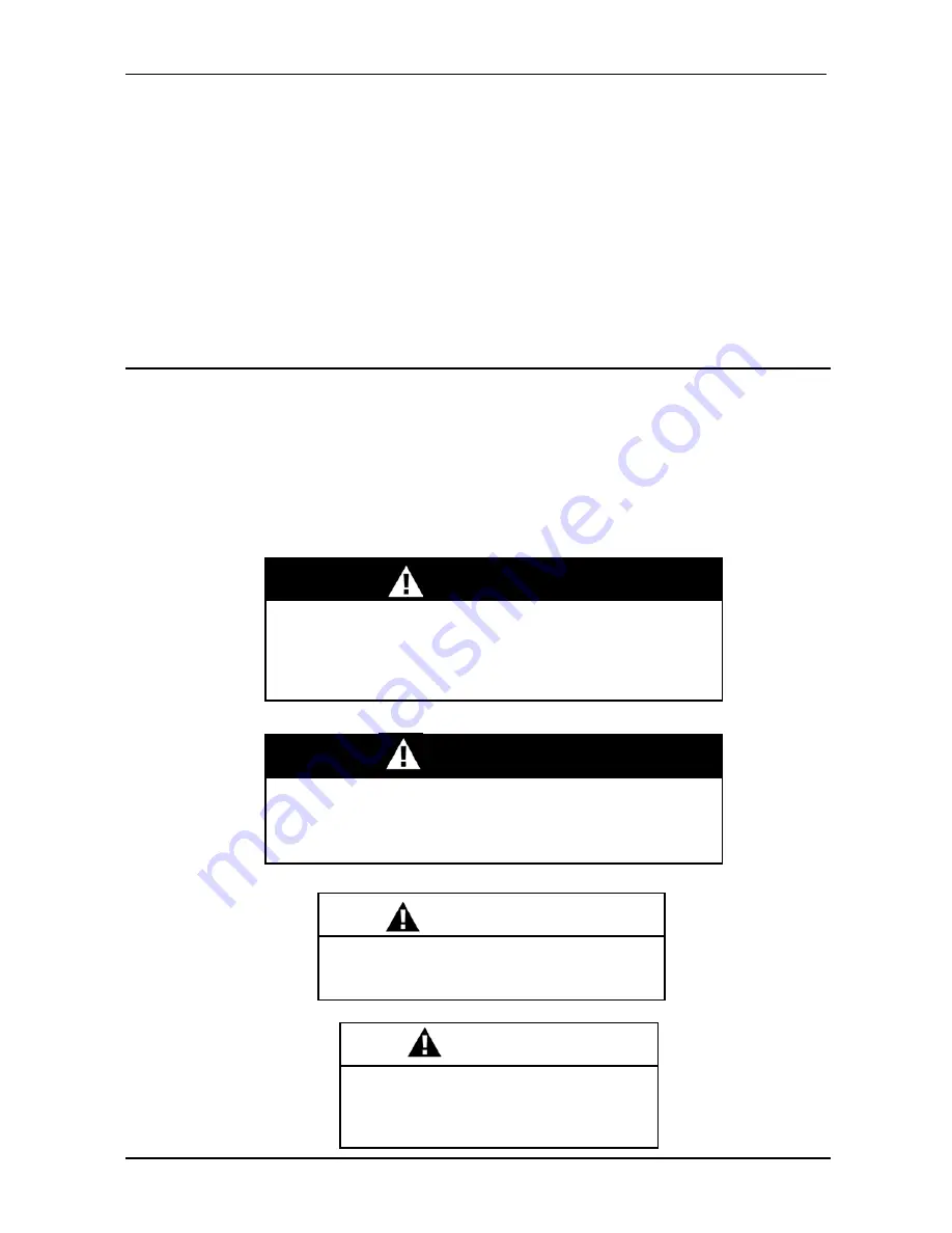
WARNING
Chlorinated solvents and aluminum are incompatible and
will cause an adverse chemical reaction, possibly resulting
in bodily injury. Under NO circumstances should
chlorinated solvents be used with the “Steady Grip
Pressure Cup”.
CAUTION
Do not exceed 100 PSIG input air pressure
into the cup. Excessive pressure could dam-
age components
WARNING
All air and fluid pressure in the system must be relieved
before servicing the cup and before cup is filled or cleaned.
Attempting to service the cup while pressurized could result
in damage to components or personal injury.


