background image

B41-818836conductiveacetal-rev0416 

Model 41-818836 Conductive Acetal Ball Valve Pump   Page 16

DIAPHRAGM  SERVICING

To service the diaphragms first 

shut off the suction, then shut off the 

discharge lines to the pump. Shut 

off the compressed air supply, bleed 

the pressure from the pump, and 

disconnect the air supply line from the 

pump. Drain any remaining liquid from 

the pump.

Step #1:

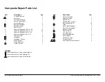
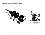
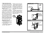
 See the pump composite 

repair parts drawing, and the diaphragm 

servicing illustration.

Using a 1/2" wrench or socket, 

remove the 16 capscrews (items 9 & 

10),  and  flanged  nuts  that  fasten  the 

elbows (items 16 and 17) to the outer 

chambers (items 13). Remove the 

elbows with the manifolds and spacers 

attached.

Step #2:

 Removing the outer 

chambers.

Using a 1/2" wrench or socket, 

remove the 16 capscrews (items 9 

and 10), and flanged nuts that fasten 

the outer chambers, diaphragms, and 

intermediate (item 4) together.

Step #3:

 Removing the diaphragm 

assemblies.

Use a 3/4" (19mm) wrench or 

six pointed socket to remove the 

diaphragm assemblies (outer plate, 

diaphragm, and inner plate) from the 

diaphragm rod (item 30) by turning 

counterclockwise.

Insert a 6-32 set screw into the 

smaller tapped hole in the inner 

diaphragm plate (item 27). Insert 

the protruding stud and the 6-32 

fastener loosely into a vise. Use a 

3/4" wrench or socket to remove the 

outer diaphragm plate (item 26) by 

turning counterclockwise. Inspect the 

diaphragm (item 14) for cuts, punctures, 

abrasive wear or chemical attack. 

Replace the diaphragms if necessary.

Step #4:

 Installing the diaphragms.

Push the threaded stud of the outer 

diaphragm plate through the center hole 

of the diaphragm. Thread the inner plate 

clockwise onto the stud. Insert the loose 

assembly with the above 6-32 fastener 

back into the vise. Use a torque wrench 

to tighten the diaphragm assembly 

together to 90 in lbs. (10.17 Newton 

meters) 120 in lbs. Santoprene (13.56 

Newton meters). Allow a minimum of 15 

minutes to elapse after torquing, then 

re-torque the assembly to compensate 

for stress relaxation in the clamped 

assembly.

Step #5:

 Installing the diaphragm 

assemblies to the pump.

Make sure the bumper (item 6) is 

installed over the diaphragm rod.

Thread the stud of the one diaphragm 

assembly clockwise into the tapped 

hole at the end of the diaphragm rod 

(item 30) until the inner diaphragm plate 

is flush to the end of the rod. Insert rod 

into pump.

Align the bolt holes in the diaphragm 

with the bolt pattern in the intermediate 

(item 4).

Fasten the outer chamber (item 

13) to the pump, using the capscrews 

(items 9 and 10) and flanged nuts. 

On the opposite side of the pump, 

pull the diaphragm rod out as far as 

possible. Make sure the bumper (item 

6) is installed over the diaphragm rod. 

Thread the stud of the remaining 

diaphragm assembly clockwise into the 

tapped hole at the end of the diaphragm 

rod (item 30) as far as possible and 

still allow for alignment of the bolt 

holes in the diaphragm with the bolt 

pattern in the inner chamber. Install 

diaphragms with convolutions facing 

towards center of pump. See sectional 

view on previous page.

Fasten the remaining outer chamber 

(item 13) to the pump, using the 

capscrews (items 9 and 10) and flanged 

nuts.

Step #6:

 Re-install the elbow/

spacer/manifold assemblies to the 

pump, using the capscrews (items 9 & 

10) and flanged  nuts.

The pump is now ready to be  

re-installed, connected and returned to 

operation.

OVERLAY DIAPHRAGM SERVICING


The overlay diaphragm (item 15) is 

designed to fit snugly over the exterior of 

the standard TPE diaphragm (item14). 


Read these instructions 

completely, before in- 

stallation and start-up. 

It is the responsibility of 

the purchaser to retain 

this manual for reference. Failure to 

comply with the recommendations stated 

in this manual will damage the pump, and 

void factory warranty.

IMPORTANT

Summary of Contents for 41-818836

Page 1: ...alve Assembly Parts List 10 Air Valve Servicing 11 Pilot Valve Servicing 12 Intermediate Assembly Drawing and Servicing 13 Check Valve Drawing 14 Check Valve Servicing 14 Diaphragm Service Drawing with Overlay 15 Diaphragm Servicing 16 Overlay Diaphragm Servicing 16 Pumping Hazardous Liquids 17 Converting the Pump for Piping the Exhaust Air 17 Exhaust Conversion Drawing 17 Converted Exhaust Illust...

Page 2: ...y enter the air end of the pump and be discharged into the atmosphere If pumping a product that is hazardous or toxic the air exhaust must be piped to an appropriate area for safe containment This pump is pressurized internally with air pressure during operation Make certain that all fasteners are in good condition and are reinstalled properly during reassembly Take action to prevent static sparki...

Page 3: ...stall design SOLIDS HANDLING Up to 125 in 3mm HEADS UP TO 100 psi or 231 ft of water 7 Kg cm2 or 70 meters DISPLACEMENT STROKE 026 Gallon 098 liter CAUTION Operating temperature limitations are as follows 190 F 88 C 10 F 23 C BINKS pumps are designed to be powered only by compressed air 190 F 88 C 20 F 29 C 220 F 104 C 35 F 37 C 180 F 82 C 35 F 37 C 275 F 135 C 40 F 40 C II 2GD T5 II 2 G c T5 II 2...

Page 4: ...at ambient conditions The use of other materials and varying hydraulic conditions may result in deviations in excess of 5 3 4 5 6 7 8 9 10 11 12 13 14 15 16 2 1 0 CAPACITY U S Gallons per minute Liters per minute 100 90 2 3 5 4 7 80 70 60 50 40 30 20 10 10 20 30 40 50 60 0 0 BAR PSI HEAD 1 2 3 4 5 6 7 0 30 20 25 10 15 5 9 1 6 7 6 3 4 5 1 5 NPSHR FEET METERS 6 10 8 13 5 10 17 12 20 14 24 16 27 100 ...

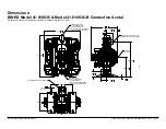
Page 5: ...RGE PORT 1 2 NPT INTERNAL 1 NPT EXTERNAL 1 2 BSP Tapered INTERNAL 1 BSP Tapered EXTERNAL 1 2 BSP Tapered INTERNAL 1 BSP Tapered EXTERNAL 7 46 189 07 2 5 46 139 9 79 249 1 42 36 3 09 78 1 75 44 1 75 44 AIR INLET 1 4 FNPT MANIFOLD CAN ROTATE 90 FROM VERTICAL CENTERLINE 4 75 121 6 09 155 4X 36 9 MTG SLOT STANDARD INTEGRAL MUFFLER CONDUCTIVE ACETAL DIMENSIONAL TOLERANCE 125 3mm Dimensions BINKS Model ...

Page 6: ...pump and the piping The flexible hose reduces vibration and strain to the pumping system A surge suppressor is recommended to further reduce pulsation in flow AIR SUPPLY Air supply pressure cannot exceed 125 psi 8 6 bar Connect the pump air inlet to an air supply of sufficient capacity and pressure required for desired performance When the air supply line is solid piping use a short length of flex...

Page 7: ...to Check Rigid pipe connections to pump Corrective Action Install flexible connectors and a Surge Suppressor What to Check Blocked air exhaust muffler Corrective Action Remove muffler screen clean or de ice and reinstall Refer to theAir Exhaust section of your pump SERVICE MANUAL What to Check Pumped fluid in air exhaust muffler Corrective Action Disassemble pump chambers Inspect for diaphragm rup...

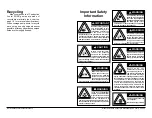
Page 8: ...this manual completely before installation and start up of the pump It is the responsibility of the purchaser to retain this manual for reference Failure to comply with the recommendations stated in this manual will damage the pump and void factory warranty WARNING Airborne particles and loud noise hazards Wear ear and eye protection B e f o r e d o i n g a n y maintenance on the pump be certain a...

Page 9: ...B41 818836conductiveacetal rev0416 Model 41 818836 Conductive Acetal Ball Valve Pump Page 7 ...

Page 10: ...HRAGM KIT Santoprene Backup Diaphragm PTFE Overlay Diaphragms PTFE Manifold O rings and FEP Encapsulated FKM O rings for metal check valve seats 41 718854 BALL AND SEAT KIT 316 Stainless Steel Check Balls 316 Stainless Steel Check Valve Seats FEP Encapsulated FKM O rings for metal check valve seats 14 15 26 4 9 31 21 9 20 6 27 32 22 32 10 10 24 5 10 9 16 33 24 2 35 35 35 35 24 10 33 13 2 24 17 10 ...

Page 11: ... 2 15 Diaphragm Overlay 2 16 Elbow Suction 2 17 Elbow Discharge 2 19 Gasket Air Inlet 1 Item Description Qty 20 Gasket Pilot Valve 1 21 Gasket Air Valve 1 22 Manifold NPT 2 Manifold BSPT Tapered 2 24 Nut Flanged 5 16 18 24 25 O ring 2 26 Plate Outer Diaphragm 2 27 Plate Inner Diaphragm 2 28 Plunger Actuator 2 29 Ring Retaining 2 30 Rod Diaphragm 1 31 Seal Diaphragm Rod 2 32 Seal Manifold 4 33 Seat...

Page 12: ...1 I 1 H 1 G 1 B 1 C 1 F 1 F 1 D 1 E MAIN AIR VALVE ASSEMBLY PARTS LIST ITEM DESCRIPTION QTY 1 Valve Assembly 1 1 A Sleeve and Spool Set 1 1 B Valve Body 1 1 C Bumper 2 1 D End Cap 2 1 E Hex Flange Capscrew 1 4 20 x 75 8 1 F O ring 4 1 G Muffler 1 1 H Muffler Cap 1 1 I Machine Screw 6 32 x 1 25 4 LEGEND Items contained within 41 718850 Air Motor Repair Kits ...

Page 13: ...ratches orothercontaminants Remove the sleeve if needed and replace with a new sleeve and spool set item 1 A Step 3 Reassembly of the air valve Install one bumper item 1 C and one end cap item 1 D with two o rings items 1 F and fasten with four hex capscrews items 1 E to the valve body item 1 B Align hole in end cap with roll pin on valve body Remove the new sleeve an spool set item 1 A from the p...

Page 14: ...wing PILOT VALVE ASSEMBLY PARTS LIST FOR MODELS EQUIPPED WITH ALUMINUM MIDSECTIONS ITEM DESCRIPTION QTY 3 Pilot Valve Assembly 1 3 A Valve Body 1 3 B Sleeve With O Rings 1 3 C O Ring Sleeve 6 3 D Spool With O Rings 1 3 E O Ring Spool 3 3 F Retaining Ring 1 LEGEND Items contained within 41 718850 Air Motor Repair Kits ...

Page 15: ... of the intermediate cavity Inspect for wear or damage Replace plunger as needed Apply a light coating of grease to each o ring and re install the plungers in to the bushings Push the plungers in as far as they will go Step 3 Re install the pilot valve assembly into the intermediate assembly Be careful to align the ends of the stem between the plungers when inserting the stem of the pilot valve in...

Page 16: ... items 13 Inspect the check balls items 2 for wear abrasion or cuts on the spherical surface The check valve seats items 33 should be inspected for cuts abrasive wear or embedded material on the surfaces of both the external and internal chambers The spherical surface of the check balls must seat flush to the surface of the inner chamfer on the check valve seats for the pump to operate to peak eff...

Page 17: ...l Valve Pump Page 15 Diaphragm Service Drawing with Overlay 24 10 26 30 6 27 14 15 26 13 10 24 10 14 15 26 30 6 27 14 13 10 24 10 9 14 9 30 6 27 18 14 26 13 10 24 10 9 18 14 26 13 9 30 6 27 14 15 26 13 10 24 10 14 15 26 13 9 30 6 27 14 9 14 Use With TPE Diaphragms Only 9 9 ...

Page 18: ...aphragm assembly together to 90 in lbs 10 17 Newton meters 120 in lbs Santoprene 13 56 Newton meters Allow a minimum of 15 minutes to elapse after torquing then re torque the assembly to compensate for stress relaxation in the clamped assembly Step 5 Installing the diaphragm assemblies to the pump Make sure the bumper item 6 is installed over the diaphragm rod Threadthestudoftheonediaphragm assemb...

Page 19: ...ng the pipe size will restrict air flow and reduce pump performance When the pumped product source is at a higher level than the pump flooded suction condition pipe the exhaust higher than the product source to prevent siphoning spills See illustration 3 at right CONVERTING THE PUMP FOR PIPING THE EXHAUST AIR The following steps are necessary to convert the pump to pipe the exhaust air away from t...

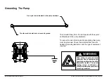
Page 20: ...rking this pump must be grounded Check the local electrical code for detailed grounding instruction and the type of equipment required Take action to prevent static sparking Fire or explosion can result especially when handling flammable liquids The pump piping valves containers or other miscellaneous equipment must be grounded WARNING WARNING One eyelet end is fastened to the pump hardware The ot...

Page 21: ... Heights IL 60139 Certifies that BINKS models 41 818810 41 818810 B 41 818820 41 818820 B 41 818822 41 818830 41 818830 B 41 818831 41 818831 B 41 818823 B 41 818836 41 818836 B Air Operated Double Diaphragm Pump comply with the European Community Directive 2006 42 EC on Machinery according to Annex VIII This product has used Harmonized Standard EN809 1998 A1 2009 Pumps and Pump Units for Liquids ...

Page 22: ...ive 2014 34 EU from April 20 2016 AODD Pumps Air Operated Double Diaphragm Pumps Directive 94 9 EC Annex VIII Technical File 203104000 1410 MER Applicable Standard EN13463 1 2009 EN13463 5 2011 DEKRA Certification B V 0344 Meander 1051 6825 MJ Arnhem The Netherlands EC EU Declaration of Conformity Manufacturer BINKS 196 International Blvd Glendale Heights IL 60139 II 2 G c T5 II 2 D c T100 C Revis...

Reviews: