


BC26 HYDRO-DRIVE Operator’s Manual
Part No 501533
11
501533_B_HI
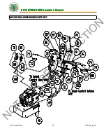
NOTE
: See
Fig 11
for proper belt routing.
TRANSAXLE
DRIVE
BELT
REMOVAL
AND
REPLACEMENT
BLADE DRIVE BELT REMOVAL AND REPLACEMENT
Belt Routing Diagram
(Top View of Machine)
DISCONNECT
spark plug wire before servicing unit.
DISCONNECT
spark plug wire before servicing unit.
Blade Drive Belt (with Transaxle
Belt not Shown)
LOOKING THROUGH TOP
Transaxle Drive Belt
(Seated below drive belt on
clutch)
1.
Disconnect spark plug wire.
2.
Lift and support the rear of the unit to allow access to the underside.
3.
Detach the spring (item 50) from the bracket (item 98) that is keeping
tension on the drive belt. (See
Fig. 9
)
4.
Walk the belt (item 121) off of the clutch (item 54) by slowly pulling the
engine over.
WARNING:
use caution not to pinch fingers between the belt
and clutch.
5.
Slip the belt off of the transaxle pulley.
6.
Replace the belt in reverse order.
NOTE
: make sure the belt is seated
properly in the clutch and transaxle and make sure that it does not bend over
the fan blades on the transaxle.
1.
Disconnect spark plug wire.
2.
Lift and support rear of unit to allow access to underside.
UNIT IS HEAVY
. Make sure support is adequate to support
weight of machine.
3.
Loosen the four screws (item 27) holding deck belt cover (item 29) and
remove cover.
4.
Follow the steps 3 and 4 in the Transaxle drive belt removal section to
remove the Transaxle drive belt.
NOTE
: It may be necessary to pry idler
pulley (item 35) away from its original position to release belt, using a
ratchet with an extension in the square hole on the idler arm should allow
the proper leverage to pull it off the belt. (See
Fig. 10
)
5.
Relieve the tension on the blade belt by pulling the deck idler arm off of the
belt. Then walk the belt off of the deck pulley.
6.
Feed the belt back to the engine base then slip the belt off of the clutch.
7.
Install the new belt in reverse order making sure the belt is seated properly
in the clutch.
8.
Reconnect spark plug wire.
Fig. 9
Fig. 10
Fig. 11
NOT
FOR
REPRODUCTION


