background image


Part No 500264 

25 

F091506B 

BC2402 Series Brush Cutter Owner’s Manual


TROUBLESHOOTING 


Problem Possible 

Cause


Corrective Action


ON/OFF switch is in OFF position. 

Move switch to START position. 

Out of gasoline. 

Fill gas tank. 

Old or contaminated gasoline. 

Drain gas tank and fill with fresh gasoline. 

Spark plug wire disconnected. 

Connect spark plug wire. 

Engine will not start. 

Dirty air cleaner. 

Clean or replace air cleaner. 

Battery low or dead. 

Charge or replace battery. 

Battery cable disconnected or corroded. 

Clean and secure battery terminals. 

Defective starter switch or wiring harness. 

Replace starter switch or wiring harness. 

Starter does not turn. 

Defective starter. 

Replace starter. 


Blade drive belt tension incorrect. 

Adjust blade drive belt tension. 

Dull blade. 

Sharpen or replace blade. 

Clogged deck. 

Unclog deck. 

Excessive debris built up on or blocking 
blade. 

Clear debris from blade area. 

Will not cut or cutting performance is poor. 

Engine RPM set too low. 

Check engine RPM. 

Blade loose or out of balance. 

Check blade for tightness. Rebalance if 
necessary. 

Engine loose. 

Check engine mounting bolts. 

Abnormal vibrations. 

Blade drive belt worn. 

Replace blade drive belt. 

Belt tension too low. 

Adjust belt tension. 

Belt worn or stretched. 

Replace belt. 

Belt slips or smokes. 

Pulleys worn or damaged. 

Replace pulleys. 

Clutch cable tension too low. 

Adjust clutch tension. 

Clutch slips or squeals. 

Clutch worn or damaged. 

Replace worn or defective clutch assembly 
parts. 

Inadequate slack in clutch cable. 

Adjust clutch cable. 

Blade brake will not engage. 

Clutch worn or damaged. 

Replace clutch/brake assembly. 

Clutch lever not releasing clutch. 

Adjust clutch cable. 

Clutch cable defective. Replace 

cable. 

Transaxle will not engage. 

Belt worn or broken. 

Replace belt. 

Transaxle will not disengage. 

Clutch cable out of adjustment. 

Adjust clutch cable. 

Debris preventing blade rotation. 

Remove debris. 

Engine will not turn over. 

Engine problem. 

Contact an authorized servicing dealer for 
your engine. 


Summary of Contents for BC2402 Series

Page 1: ...Part No 500264 1 Form No F091506B BILLY GOAT BC2402 Series Brush Cutter Owner s Manual Patent Number D386768...

Page 2: ...Cutting 13 Shut Down 14 Cutting Height Adjustment 14 Clearing a Clogged Cutting Deck 14 Handling and Transporting 15 Storage 15 Maintenance 16 Periodic Maintenance 16 Cleaning 16 Blade Removal and Sha...

Page 3: ...27 3 kg Unit Weight 266 lb 120 7 kg 278 lb 126 4 kg 291 lb 132 3 kg 273 lb 124 1 kg In accordance with 2000 14 EEC standards 106 dB a 106 dB a 106 dB a 106 dB a Sound at Operator s ear 93 dB a 93 dB a...

Page 4: ...utter This symbol indicates the engine oil level should be checked before operating this equipment Read and make sure you thoroughly understand the following safety precautions before assembling opera...

Page 5: ...perate engine with grass leaves or other combustible material near the muffler DO NOT touch muffler cylinder or cooling fins when hot Contact with hot surfaces may cause severe burns DO NOT leave equi...

Page 6: ...761mm Hg VIBRATION DATA VIBRATION LEVEL 5g 4 87 m s2 Vibration levels at the operator s handles were measured in the vertical lateral and longitudinal directions using calibrated vibration test equip...

Page 7: ...correct position for each label may be determined by referring to the Figure and Item numbers shown PN 400268 See Figure 6 Item 169 PN 890254 See Figure 6 Item 188 PN 500349 See Figure 6 Item 186 Ite...

Page 8: ...Part No 500264 8 F091506B BC2402 Series Brush Cutter Owner s Manual Brush Cutter Assembly Drawing Figure 1...

Page 9: ...spark plug wire before assembling unit 2 Remove mounting hardware 144 143 115 117 141 from lower handles 51 and 52 3 Loosen but do not remove four screws 115 securing the lower handles 51 and 52 4 Att...

Page 10: ...NOT operate equipment with bystanders in or near the work area DO NOT operate equipment with guards removed DO NOT operate equipment in areas containing rock glass string like material wire rags cans...

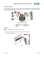
Page 11: ...ped firmly and which allows sufficient leverage to steer the machine Operator s controls are shown below Operator Control Locations 1 Blade Clutch Lever 5 ON OFF Switch 2 Gear Shift Lever 6 Drive Clut...

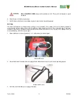
Page 12: ...nda engine only Choke 4 Units equipped with electric starters Press and hold ON OFF button until engine starts ON OFF I O Switch I ON O Off Manual start shown DO NOT START equipment with drive or blad...

Page 13: ...of the cut is directly related to ground speed during cutting Under most conditions cutting should be done in first or second gear Third gear should be reserved for conditions where weeds and brush a...

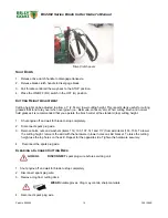
Page 14: ...ecommended that you operate the brush cutter at the standard top cutting height 1 Shut engine off and wait for blade to stop completely 2 Disconnect spark plug wire 3 Remove bolts nuts and washers ite...

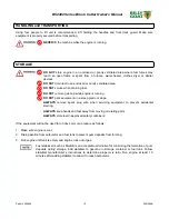
Page 15: ...rk equipment on a steep grade or slope ALWAYS remove spark plug wire when servicing equipment to prevent accidental starting ALWAYS keep hands and feet away from moving or rotating parts ALWAYS store...

Page 16: ...e and linkage z Check blade clutch cable tension z Inspect battery for corrosion damage or leaks electric start units only z Apply anti seize compound to rear axles z Check battery strap for excessive...

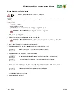
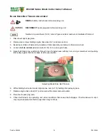
Page 17: ...it to allow access to underside UNIT IS HEAVY Make sure support is adequate to support weight of machine 3 Block blade to prevent it from rotating during removal 4 Remove blade bolt 8 139 lock washer...

Page 18: ...y and amount of tension on belt 4 Loosen but do not remove two nuts 6 116 on top on engine base 5 Reset belt tension by reaching in through top of engine base with pry bar or long screwdriver and push...

Page 19: ...clutch should require 10 lbs of force to depress the end of the clutch lever The blade clutch cable spring should stretch 1 4 to 3 8 6 4 9 5 mm 3 Adjust cable tension by tightening or loosening cable...

Page 20: ...It may be necessary to pry idler pulley 8 9 away from its original position to release belt 5 Using drive extension and universal joint loosen but do not remove four screws 6 107 holding belt guides...

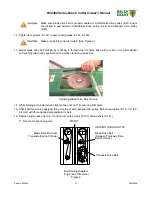
Page 21: ...ewdriver and pushing idler pulley against belt to increase tension see below Adjusting Blade Drive Belt Tension 14 While holding belt under tension tighten two nuts 6 116 securing idler plate 15 Check...

Page 22: ...ing adjustment may be required to maintain proper cable tension and clutch engagement A properly adjusted transaxle drive clutch should require 3 lbs of force to depress the end of the clutch lever 3...

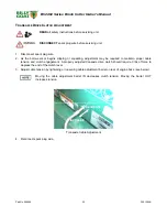
Page 23: ...d support rear of unit to allow access to underside UNIT IS HEAVY Make sure support is adequate to support weight of machine 3 Using drive extension and universal joint loosen but do not remove four s...

Page 24: ...RAMS Starter Switch Wiring Figure 3 Starter Circuit Schematic Diagram Figure 4 ON OFF Switch Circuit Schematic Diagram Figure 5 SWITCH WHITE RED STARTER SOLENOID BATTERY BLACK 20A FUSE RED STARTER MOT...

Page 25: ...de area Will not cut or cutting performance is poor Engine RPM set too low Check engine RPM Blade loose or out of balance Check blade for tightness Rebalance if necessary Engine loose Check engine mou...

Page 26: ...e taken to the dealer from whom it was purchased or to an authorized Servicing BILLYGOAT Dealer The owner must present the remaining half of the Warranty Registration Card or if this is not available...

Page 27: ...Part No 500264 27 F091506B BC2402 Series Brush Cutter Owner s Manual MAINTENANCE RECORD Date Service Performed...

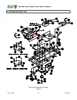
Page 28: ...Part No 500264 28 F091506B BC2402 Series Brush Cutter Owner s Manual ILLUSTRATED PARTS LIST Engine and Engine Base Assembly Figure 6...

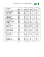
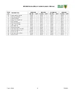
Page 29: ...60002 8 8160002 8 8160002 10 8160002 10 118 Bolt Carriage 5 16 18 x 1 8024040 2 8024040 2 8024040 2 8024040 2 120 Washer 3 8 FC 8171004 1 8171004 1 8171004 1 8171004 1 121 Terminal Piggyback 3 16 8900...

Page 30: ...Part No 500264 30 F091506B BC2402 Series Brush Cutter Owner s Manual Handlebar Assembly Figure 7...

Page 31: ...41035 1 8041035 1 8041035 1 115 Screw Cap 5 16 18 x 2 8041032 4 8041032 2 8041032 4 8041032 2 117 Nut Lock 5 16 18 8160002 10 8160002 10 8160002 10 8160002 10 119 Screw Cap 5 16 18 x 1 1 2 8041030 4 8...

Page 32: ...Part No 500264 32 F091506B BC2402 Series Brush Cutter Owner s Manual Transaxle and Blade Deck Assembly Figure 8...

Page 33: ...9 11 8041029 11 104 Washer Split Lock 5 16 8177011 5 8177011 5 8177011 5 8177011 5 107 Screw Cap 5 16 18 x 1 8041028 8 8041028 8 8041028 8 8041028 8 108 Screw Cap 5 16 18 x 2 3 4 8041035 4 8041035 4 8...

Page 34: ...Part No 500264 34 F091506B BC2402 Series Brush Cutter Owner s Manual Blade Drive Spindle Assembly Detail Drawing Figure 9...

Page 35: ...2 36 Shaft Drive Blade 500107 1 500107 1 500107 1 500107 1 37 Spacer Spindle Bearing 500115 1 500115 1 500115 1 500115 1 38 Pulley 7 OD x 7 8 Bore 500253 1 500253 1 500253 1 500253 1 53 Adapter Blade...

Page 36: ...ush Cutter Owner s Manual If you liked this product please feel free to view our full line of quality lawn care renovation and debris removal products at www billygoat com AERATOR POWER RAKE QL VACUUM...

Reviews: