BIG RBX5 Operation Manual Download Page 4

Caution

Before installing a cutting tool, always use, on the internal diameter of the chuck, the internal and 

external surfaces of the collet and on the shank of the cutting tool, kerosene or other degreasing 

agents and wipe the dirty parts with a cloth.

Warning

The Air Turbine Spindle rotates at very high speed.  In case of using cutting tools with a big 

unbalance  or  tools  with  small  diameter  and  long  overhang,  due  to  the  centrifugal  force,  the 

cutting tool may break creating an extremely dangerous situation.  Use a cutting tool with high 

rigidity and make it short as much as possible.

SPECIFICATIONS

UTILIZATION PROCEDURES

Clamping range (mm)
Tool diameter (mm)
Minimum spindle speed (min

-1

)

Maximum spindle speed (min

-1

)

Collet

ø0.45 - 4.05
ø1.5 or smaller
About 40,000 (0.3MPa)
About 50,000 (0.6MPa)
NBC4S-dAA (Option)

ø0.45 - 4.05
ø1.5 or smaller
About 60,000 (0.3MPa)
About 80,000 (0.6MPa)
NBC4S-dAA  (Option)

Type

RBX5 / RBX5C

RBX7 / RBX7C

BIG-PLUS is a standard product of BIG Daishowa Seiki.  Use machine tools with the 

BIG-PLUS trademark to obtain a correct double face contact.  BIG-PLUS holders are 

also compatible with spindles of standard machines.  In this case, check that there 

are not projecting objects in the machine spindle’s surface and in the holder’s surface.

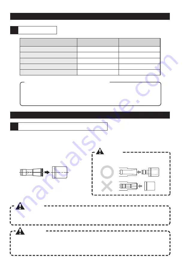
How to install / remove a cutting tool

1

Specifications

1

About BIG-PLUS (BBT, BDV, and BCV)

Use the X-Wrench and the Mega Wrench for install/remove the cutting tool.  Please consult P4 “How 

to use the X-Wrench” regarding how to use the X-Wrench.

Always install the collet in the chuck body 

after have inserted it into the nut.

Caution

Insert the collet from the rear part of the nut 

and push it until the ribbed part of the collet is 

set with a “click”.

It is possible to remove the collet from the nut 

by pulling the collet straight along the spindle.

[Collet installation procedures]

[Collet removal procedures]

3

Summary of Contents for RBX5

Page 1: ...ve a cutting tool 2 Initial rotation of the air turbine 3 Spindle speed adjustment 4 Concerning the use of coolants 5 Air nozzles adjustment 6 Pull stud bolts installation INSTALLATION 1 Installation...

Page 2: ...s provided with holes sold apart Caution Please reduce the ATC speed The impact with the ATC may damage the cutting tool in case of using tools with small diameter Warning Do not touch the cutting too...

Page 3: ...nozzles adjustment P8 5 Concerning the use of coolants P7 4 Spindle speed adjustment P6 3 Initial rotation of the air turbine P6 2 Specifications P3 1 Concerning the air supply P17 4 In order to be ab...

Page 4: ...smaller About 60 000 0 3MPa About 80 000 0 6MPa NBC4S dAA Option Type RBX5 RBX5C RBX7 RBX7C BIG PLUS is a standard product of BIG Daishowa Seiki Use machine tools with the BIG PLUS trademark to obtain...

Page 5: ...e handle as shown in the picture Insert the wrench on the flange part of the spindle and move it on the LOCK side XW27 C O L K E O P N 1 2 3 X Wrench XW27 How to install a cutting tool The X Wrench is...

Page 6: ...T I R at the base of the cutting tool s shank Insert the MEGA Wrench on the nut with the LOCK seal facing up and execute the tightening process with both hands Recommended tightening torque 3N m O P...

Page 7: ...speed after have adjusted the air pressure and started the air supply Air pressure for the warming up operation Warming up time 0 3MPa More than 10 min Time required for reaching the target speed Init...

Page 8: ...to prevent coolants and oil mists from invading the internal parts of the holder However if the coolant is applied directly on the spindle body it may invade its internal parts Pay attention to not a...

Page 9: ...nozzles adjustment 5 Pull stud bolts installation 6 Always respect the recommended torque when clamping the pull stud bolts In particular for BBT30 exceeding the recommended values will easily bulge t...

Page 10: ...and the measures of K1 and D of the Air Turbine Spindle to check that there is no interference between the ATC arm of the machining center and the Air Turbine Spindle Please inquiry the machine manuf...

Page 11: ...he ditches and the internal parts of the block To the customers that currently use our High Jet Holder High Spindle etc and have already installed the locating block in the machines Even if the locati...

Page 12: ...that a clutch movement of the locating pin higher than the prescribed amount 6mm will exert an eccentric load on the case and add an anomalous load to the bearings leading to heat and a reduction of t...

Page 13: ...th the following formula and calculate the length B of the locating pin How to adjust the length of the locating pin Loosen the set screw of the locating collar then loosen the nut and the locating co...

Page 14: ...indexing ring to the setting angle used on your machine by matching exactly the line marker on the main body Refer to the figure on the right Tightening the side lock After the adjustment apply the a...

Page 15: ...the indexing ring to the setting angle used on your machine by matching exactly the line marker on the main body Refer to the figure on the right Tightening the lock bolts After the adjustment apply...

Page 16: ...K1 D BBT shank HSK shank D K1 K1 D Gauge line For safety reasons be sure to check the following notes before the installation on the machining center Use as base of the interference values written in...

Page 17: ...n bar however if the machine s spindle is rotated by mistake this may twist the air tube causing severe accidents Insert as shown in the figure on the right the anti rotation bar with its flat part fa...

Page 18: ...e air the following device is recommended Even when using the center through type always use a filter mesh 0 01mm or above to supply pure air from the machine s spindle Mist separator Mesh 0 3 m Mesh...

Page 19: ...on for 45 to remove it Element removal Apply round pincers to the cylindrical part of the element and turn them to the left for removing the element Element installation Apply round pincers to the cyl...

Page 20: ...dify the unit Otherwise it will be considered outside the normal overhaul or repairs It is recommended to perform the overhaul after 1 year from the first operation or when the operation time exceeds...

Reviews: