background image

3-4

PPT0104-901336

3.

Charge batteries in accordance with hydrometer
readings.

NOTE:

A fully charged battery has a specific
gravity of 1.260 to 1.275.

4.

After charging, again check water level in each cell
of the flooded cell batteries. Water level must cover
plates but not be higher than the base of the
battery cell filler neck.
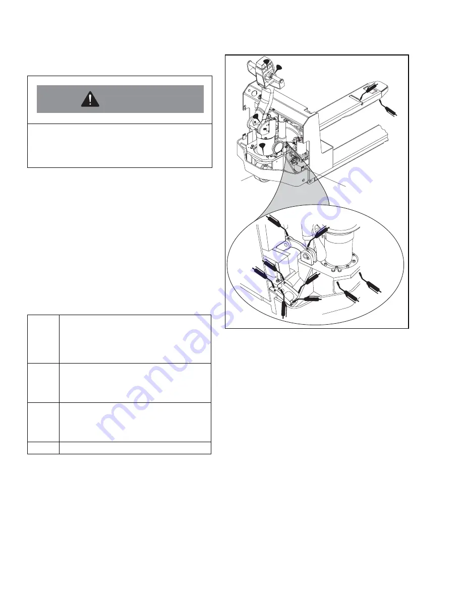
3-5. LUBRICATION

Refer to Table 3-3 for recommended types of grease
and oil. Table 3-3, in conjunction with Figure 3-1,
identifies the items requiring periodic lubrication and
where they are located on the lift truck.

Table 3-3. Recommended Lubricants 

(See Table 3-4 for Application)

Figure 3-1. Lubrication Locations

Do not service batteries while they are being
charged. 

Do not connect or disconnect battery from
charger while charger is on.

No. 1

Transmission oil - EP SAE 80W-go. 
Capacity - 1.5 quart. Big Joe No. 055780 
(Replace with 055790. 1W-30, if cold 
conditioning option for continuous 
operation below 320F is installed).

No. 2

Grease-Lithium base, general purpose. Big 
Joe No. 055750 (Replace with 055753 if 
cold conditioning option for continuous 
operation below 320F is installed).

No. 3

Hydraulic oil. Big Joe No. 900855 (Gallon) 
or 900893 (Quart). (Replace with 055784 if 
cold conditioning option for continuous 
operation below 320F is installed)

No. 4 

Engine lubricating oil - No. 20

WARNING

I-7044

Summary of Contents for PPT 45 Series

Page 1: ...PPT0104 901336 i PPT 45 Series Self Propelled Pallet Lift Truck Serial Numbers 373323 through 374781 Operation Maintenance Repair Parts List Manual No 901336...

Page 2: ...ing the servicing of the PPT 45 it may be required to work with and around electrical power In most cases the truck will be serviced with the batteries disconnected However some of the service procedu...

Page 3: ...3 MAINTENANCE 3 1 GENERAL 3 1 3 2 OPERATOR DAILY CHECKS 3 1 3 3 MONTHLY AND QUARTERLY CHECKS 3 1 3 4 BATTERY CARE 3 1 3 4 1 General 3 1 3 4 2 Battery Removal 3 3 3 4 3 Testing and Charging of Lead Aci...

Page 4: ...l and Replacement 4 20 4 7 2 Battery Cable Assemblies Replacement 4 20 4 7 3 Transistor Contactor Panel 4 21 4 7 4 Horn Replacement 4 22 4 7 5 Battery Charger 4 23 4 7 5 1 12V Light Duty Gel Cell Batt...

Page 5: ...ng 6 13 6 6 1 Check for Power to the Controller 6 14 6 6 2 Check for Contactor Operation and Keyswitch Input KSI 6 14 6 6 3 Check Potentiometer Circuitry 6 14 6 6 4 Check for controller output 6 15 SE...

Page 6: ...vi PPT0104 901336...

Page 7: ...rolled by pushbuttons located on the control head The battery powered lift truck is quiet and without exhaust fumes The reversible DC motor propels the lift truck in forward or reverse direction throu...

Page 8: ...sistant hand grips to provide a firm hand hold for operator Flow control valve regulates maximum load lower ing speed within prescribed limits Relief valve maintains hydraulic pressure within prescrib...

Page 9: ...when traveling without load as the risk of overturn may be greater 6 Always look in direction of travel Keep a clear view and when load interferes with visibility travel with load or lifting mechanis...

Page 10: ...occurs when the handle is released and spring action raises it to the upright position 2 4 DRIVING AND STOPPING PROCEDURES 2 4 1 Standard Travel 1 If equipped turn on the key switch Grasp the grips of...

Page 11: ...d height To lower the forks push in LOWER button and hold until forks descend to desired height 2 8 LOADING AND UNLOADING 1 Move truck to location where load is to be picked up 2 Using the BACKWARD sp...

Page 12: ...2 4 PPT0104 901336 NOTES...

Page 13: ...extended by giving them proper care Perform a daily check of the batteries whether or not the equipment is in daily use If the truck is found to be in need of repair unsafe or contributes to an unsaf...

Page 14: ...rning labels data plates etc are in the same condition as originally equipped FRAME AND SERVICE COVER Check for damaged paint cracks in welds or other damage OPERATIONAL CHECKS HORN Check for sound ST...

Page 15: ...check condition of commutator brushes and springs Section 4 5 Monthly Clean hydraulic pump motor and check condition of commutator brushes and springs Section 4 8 Monthly Check brake for proper opera...

Page 16: ...Recommended Lubricants See Table 3 4 for Application Figure 3 1 Lubrication Locations Do not service batteries while they are being charged Do not connect or disconnect battery from charger while char...

Page 17: ...4 Application of Lubricant Semi Annually Steering Arm Elbow Oil Can No 4 1 or 2 drops each time serviced Annually 2 Transmission Housing Can No 1 Fill to plug level Semi Annually 1 Hydraulic Reservoir...

Page 18: ...3 6 PPT0104 901336 NOTES...

Page 19: ...he part number is NP order the next higher assembly If the part number is VAR order by part name with truck model number and serial number If the part is listed with more than one part number select t...

Page 20: ...0 and 66 3 Check gap between rollers on directional switches 7 and surface of cam 46 If required adjust position of bracket 50 to obtain a 0 03 0 06 inch clearance 4 Disconnect the connector round loc...

Page 21: ...ver 66 bottom cover 40 and switch plate 67 2 Refer to Section 4 3 1 if necessary to gain access to a defective belly button switch NOTE Switch operation may be checked with a continuity light containi...

Page 22: ...e 67 and secure with screws 22 and 23 l Install top cover 66 and secure with screws 64 m Install bottom cover 40 and secure with screws 20 n Connect the battery 4 3 4 Steering Arm 1 Steering Arm Retur...

Page 23: ...ll remain inside the spring tube 25 h Remove steering arm return spring 24 from spring tube 25 If spring is severely jammed and will not come loose use punch and drive the 1 4 inch diameter roll pin 2...

Page 24: ...enough slack to enable connection to the control head 9 Remove the four screws 1 Figure 4 6 from the ring guard 3 and slide the guard upwards 10 Remove the two cable clamps to free drive motor and con...

Page 25: ...ons 1 through 12 respectively in the new connector See Figure 4 7 20 Reattach the round control cable connector 54 Figure 4 5 within the motor compartment 21 Reinstall the control head assembly attach...

Page 26: ...e assembly NOTE Use caution when removing the steering arm that brake and control head cables are not disconnected or damaged 6 Locate the rubber seal on the brake assembly 1 Figure 4 8 Slide the rubb...

Page 27: ...ower groove in the armature 9 Reinstall the steering arm 10 Remove blocking and lower truck 11 Reconnect the battery and test the brake function 12 Repeat brake adjustment as needed to make sure that...

Page 28: ...e three brake assembly mounting bolts 1 Torque the bolts to 17 ft lbs 23 Nm 13 Adjust the brake air gap See Section 4 4 1 Brake Pad Adjustment 14 Slide the rubber cover seal into place 15 Reinstall th...

Page 29: ...d and blue wires as close to the crimp on connector as possible NOTE A new crimp on connector is included with the replacement brake assembly 9 Remove the old brake assembly 2 Figure 4 12 10 Install n...

Page 30: ...an Switch 4 4 5 Replacement of Creep Travel Switch 1 Disconnect the battery 2 Block the wheels to prevent the truck from rolling 3 Remove the steering tube cover plate 2 Figure 4 6 4 Remove screws 3 F...

Page 31: ...l of the control arm Figure 4 15 Control Arm Shock Absorber 4 5 DRIVE MOTOR TRANSMISSION DRIVE WHEEL AND PIVOT TUBE ASSEMBLY 4 5 1 Drive Motor Servicing The drive motor exposed surfaces should be clea...

Page 32: ...tor compartment covers 6 8 and 10 4 Remove the four screws 1 securing the guard ring 3 and slide the guard ring upwards as much as possible 5 Remove the four screws 23 Figure 4 4 securing the steering...

Page 33: ...ivot tube cap 2 Figure 4 6 from the pivot tube 6 Label and disconnect wires leading to the deadman switch and creep travel switch 7 Remove four control head mounting screws and control head then disco...

Page 34: ...bly 22 Reconnect the battery 23 Test operate the lift truck 4 5 5 Transmission Assembly Removal NOTE The transmission does not have any user serviceable parts If the transmission is the cause of trave...

Page 35: ...ise the load wheels off the floor Securely block the forks in the raised position by positioning supports under both fork tips 4 Drive the roll pin 3 Figure 4 21 from the load wheel shaft 5 and pull t...

Page 36: ...either extend or retract the hydraulic cylinder to gain access to the roll pin Using a fine tip marker draw a match mark line across the end of the lift link support pin and onto the link lift shaft...

Page 37: ...rn or damaged U clip nuts as needed Removal of components mounted on power section frame may be necessary to complete repairs welding of frame refer to table of contents for identification of instruct...

Page 38: ...y Cable Assemblies Replacement 1 Disconnect batteries Section 4 7 1 2 Trace the cable 1 Figure 4 24 that needs to be replaced from the battery compartment into the motor compartment 3 Remove the cable...

Page 39: ...emoval a Disconnect the battery b Remove screws 5 7 and 9 Figure 4 6 lock washers flat washers and motor compartment covers 6 8 and 10 c Refer to Figure 4 25 and tag and disconnect all electrical wire...

Page 40: ...stall motor compartment service cover and secure d Connect the battery 4 7 4 Horn Replacement To replace the horn proceed as follows 1 Tag and disconnect all electrical connections from horn 2 Remove...

Page 41: ...batteries plug the charger into 110 V AC power 4 7 5 2 Medium Duty 6V Battery Pack The medium duty battery pack is a self contained unit with batteries and charger built into the battery case The cha...

Page 42: ...arge when hydrometer shows a specific gravity of 1 260 to 1 275 NOTE If the Discharge Indicator does not function properly check the 5 Amp fuse located on the rear side of the indicator before replaci...

Page 43: ...d diode to the new hour meter 2 e Install the new hour meter into the panel and secure with the 3 screws lock washers and nuts f Connect the battery 4 7 8 KEYSWITCH The optional key switch is item 3 F...

Page 44: ...6 NEG POS NEG NEG POS NEG POS 1 2 3 3 2 1 3 2 1 A2 F2 A1 F1 F1 A2 3 3 15 1 2 15 3 3 3 BLACK GREEN BLACK WHITE 19 19 19 16 17 20 BLACK 18 WHITE RED BLACK RED GREEN BLACK 19 20 GR BLUE BLACK RED WHITE W...

Page 45: ...System 4 8 2 Hydraulic Pump Motor and Reservoir Assembly The hydraulic pump motor and reservoir assembly can be disassembled and repaired The motor and control valves can be repaired however a defecti...

Page 46: ...il under pressure can penetrate the skin It is toxic and can damage tissue Always use a piece of wood or cardboard to check for suspected hydraulic leaks NEVER USE YOUR HANDS Obtain immediate medical...

Page 47: ...d as follows 1 Secure the lift cylinder in a vise clamping lightly at the base of the cylinder 2 With spanner wrench remove the cylinder head 2 Figure 4 33 from the cylinder weldment 7 3 Withdraw the...

Page 48: ...tor compartment service cover 4 9 DECALS AND TRIM 4 9 1 Painting Requirements Clean all dirt scale and other foreign matter from surfaces to be painted Touch up paint on frames and pull rods with yell...

Page 49: ...s meat lockers and freezers requires the changing of oils and grease and modification of the control head and deadman switch as shown in Figure 5 1 For intermittent operation under 32 F the oils and g...

Page 50: ...5 2 PPT0104 901336 NOTES...

Page 51: ...perating position and control lever is in reverse reverse switch is defective If voltage is present contactor is defective Truck runs in reverse but not in forward Defective switch in control head or...

Page 52: ...ol switch and lowering valve look for blockage in hydraulic line Repair adjust as required Load will not hold a Oil bypassing internally between check valve and adapter body b Worn lift cylinder seal...

Page 53: ...problem is in the contactor unit and the contactor must be disassembled and detective parts replaced Figure 6 1 Contactor Testing 6 2 2 Switch Testing 1 Disconnect the battery 2 Set the VOM test meter...

Page 54: ...11 10 9 8 7 6 5 4 2 1 12 11 10 9 8 7 6 5 4 3 2 1 1 2 3 4 5 6 7 8 9 10 11 12 13 14 15 16 3 3 9 8 6 12 10 COM N C N O 8 N C 5 6 3 1 N O N C COM COM N O 2 COM N O N C COM N C N O COM 6 N C N O 12 12 2 8...

Page 55: ...stor Controller Schematic 3 3 1 2 3 4 5 6 7 8 9 10 11 12 13 14 15 1 2 3 4 5 6 7 8 9 10 11 12 3 3 3 3 12 11 10 9 8 7 6 5 4 2 1 9 8 6 5 10 3 3 13 3 5 5 5 12 NEG POS 2 3 7 8 8 16 11 7 1 9 14 13 5 3 4 13...

Page 56: ...Current Multiplication During acceleration and during reduced speed operation the controller allows more current to flow into the motor than flows out of the battery The controller acts like a DC tran...

Page 57: ...cover and an equilibrium is established in which the battery supplies as much current as it can without falling below the minimum voltage cutoff 7 Over voltage Protection As with the under voltage pro...

Page 58: ...eck M output fault Memory checks upon start up Over voltage cutback Power supply out of range internal Throttle fault Under voltage cutback Watchdog external and internal Watchdog internal 11 Hand Hel...

Page 59: ...HECKOUT Carefully complete the following checkout procedure If you find a problem during the checkout refer to Section 5 for further information The checkout can be conducted with or without the handh...

Page 60: ...h pedal disable HPD static return to off SRO and anti tie down are as desired 10 Check to see whether the emergency reverse belly button feature is working correctly Verify that the circuit is operati...

Page 61: ...g Chart at the beginning of this section Operational faults such as an over temperature situation are cleared as soon as the operation is brought within range Non operational faults such as a throttle...

Page 62: ...ows the controller to accumulate a new file of faults By checking the new diagnostic history file at a later date you can quickly determine whether the problem has been completely fixed To clear the d...

Page 63: ...basic wiring schematic Figure 6 3 when conducting these tests Make sure the controller is hooked up as shown in Figure 6 4 Refer to the wiring diagram and schematic for your vehicle These tests requi...

Page 64: ...r to the controller B terminal and the voltmeter to the controller s KSI terminal pin 16 wire 3 on the multi pin connector to the controller 4 If the contactor coil and KSI terminal are not getting vo...

Page 65: ...hat you buy an ammeter of the type that is simply held against the wire being tested These are available for a low cost at auto parts stores Though the accuracy of these meters is not great they are a...

Page 66: ...6 16 PPT0104 901336 NOTES...

Page 67: ...PPT0104 901336 7 1 Section 7 PARTS LIST...

Page 68: ...7 2 PPT0104 901336 7 1 CONTROL HEAD ASSEMBLY Figure 7 1 Control Head Assembly Push Button Switch Assembly High Speed Cutout Switch Assembly I 7007...

Page 69: ...l Pin 1 4X15 16 2 16 060942 Roll Pin 1 8X1 1 4 2 17 061016 Roll Pin 1 4X3 2 18 061200 01 Spirol Pin 3 16X1 1 19 061750 E Retainer Ring 2 20 067416 Pan HD Screw 6 32X1 2 4 21 068180 Round HD Screw 4 40...

Page 70: ...7 4 PPT0104 901336 7 1 CONTROL HEAD ASSEMBLY CONTINUED Figure 7 1 Control Head Assembly Push Button Switch Assembly High Speed Cutout Switch Assembly I 7007...

Page 71: ...01 Wire Assembly 5 50 505052 Switch Bracket Assembly 1 51 066052 Thumb Screw 6 32 1 52 800272 Control Lever 2 53 800273 Control Handle 1 54 800274 Safety Cover 1 55 023201 Wire Harness Assembly 1 56 0...

Page 72: ...7 6 PPT0104 901336 7 2 STEERING ARM Figure 7 2 Steering Arm Assembly 1 3 2 4 5 7 8 9 10 11 12 31 14 13 15 16 17 18 19 20 24 23 21 22 25 26 27 28 8 30 9 29 12 11 10 32 I 7057...

Page 73: ...Button Head Nylok 13 2 059426 Nut Plain Hex 14 2 077210 Washer Lock 15 1 285302 Pin Spring 16 1 285303 Pin Spring 17 1 052922 Bushing Flange Bronze 18 1 800204 Clamp Tube 19 1 401127 Spacer 20 1 06556...

Page 74: ...7 3 Power Section Parts TO DRIVE MOTOR TO CONTACTOR PANEL 1 2 46 45 44 43 42 41 40 39 39 5 8 7 6 5 16 3 4 5 6 7 8 5 10 11 17 18 21 30 26 19 13 8 15 20 22 21 23 24 25 26 27 28 29 31 32 33 34 35 36 37 3...

Page 75: ...y 13 4 506137 Pin Keeper 14 Not Used 15 4 065476 Screw HHCS 20 UNC x 1 2 Long 16 1 504096 Suppressor Assembly Spike Horn 17 8 065531 Screw BHCS 10 32 UNC x Long 18 2 077207 Washer Lock 10 19 1 009602...

Page 76: ...gure 7 3 Power Section Parts TO DRIVE MOTOR TO CONTACTOR PANEL 1 2 46 45 44 43 42 41 40 39 39 5 8 7 6 5 16 3 4 5 6 7 8 5 10 11 17 18 21 30 26 19 13 8 15 20 22 21 23 24 25 26 27 28 29 31 32 33 34 35 36...

Page 77: ...7211 Washer Lock 3 8 38 2 064605 Screw HHCS 3 8 16 UNC 1 Long 39 1 023266 Cable Assembly Control 40 1 901451 Oversleeve Cable Braided 41 1 023272 Wire Harness Assembly Brake Switches 42 1 021257 Termi...

Page 78: ...7 12 PPT0104 901336 7 4 TRANSMISSION MOTOR AND BRAKE ASSEMBLY Figure 7 4 Transmission Motor and Brake Assembly 12 10 14 15 16 7 9 8 13 6 11 2 1 3 4 5 17 18 19 20 21 22 23 25 26 27 24 2 1 3 4 5 I 7051...

Page 79: ...tersunk Metric M8 x 1 25 x 35 Lg 10 1 404189 Motor End Plate 11 8 901708 Screw Hex Socket FL HD M8 x 35 mm Long 12 1 016051 Motor 13 1 901709 O ring 14 1 901710 Woodruff Key 15 1 901711 Gear Spiral 16...

Page 80: ...7 14 PPT0104 901336 7 5 DRIVE MOTOR REPAIR PARTS Figure 7 5 Drive Motor Repair Parts 1 2 5 6 7 9 8 4 3 13 14 15 11 10 12 I 7022...

Page 81: ...ountersunk Screw Metric 5 1 404189 Motor End Plate 6 4 901725 Bolt Hex Head 7 1 901726 Head Commutator End 8 1 901727 Brush Lead and Terminal Connector 9 1 901728 Bearing Commutator End 10 1 901729 Br...

Page 82: ...7 16 PPT0104 901336 THIS PAGE INTENTIONALLY LEFT BLANK...

Page 83: ...C x Long 2 1 404221 Cover Brake 3 1 404220 Ring Guard 4 7 059940 01 Nut Retainer 20 5 2 065525 Screw BHCS 20 UNC x 5 8 Long 6 1 506144 Cover Main 7 5 065527 Screw BHCS 20 UNC x 1 0 Long 8 1 404217 Cov...

Page 84: ...FORK SECTION PARTS Figure 7 7 Fork Section Parts 7 8 9 13 10 7 2 2 2 1 5 4 3 6 3 14 23 24 25 26 27 24 THREADED STUDS WELDED TO MOTOR COMPARTMENT WALL 11 12 12 10 10 11 11 22 TO CONTROLLER 21 16 17 18...

Page 85: ...1 506125 Torsion Tube 9 2 506126 Pin Keeper 10 8 077209 Washer Lock 11 6 065476 Screw HHCS 20 UNC x 1 2 Long 12 2 506141 Assembly Link 13 4 506137 Pin Keeper 14 4 077204 Washer Lock 6 15 Not Used 16 2...

Page 86: ...7 20 PPT0104 901336 THIS PAGE INTENTIONALLY LEFT BLANK...

Page 87: ...Parts 1 2 3 4 6 5 I 7052 Item No Qty Part No Description 1 506154 Hydraulic Cylinder Assembly 1 1 901735 O ring 2 1 901736 O ring 3 1 901737 Seal 4 1 901738 Seal 5 1 025716 Grease Fitting Straight 28...

Page 88: ...7 22 PPT0104 901336 7 9 HYDRAULIC CYLINDER PARTS Figure 7 9 Hydraulic Pump Motor and Reservoir Assembly Parts 2 3 1 6 4 15 14 16 5 13 10 11 12 9 8 7 I 7058...

Page 89: ...er 4 1 901437 Adapter Pump Res Kit 5 1 025535 9 16 Elbow 6 1 901442 Relief Valve Assy 7 1 901440 Filter 8 1 901441 Reservoir 9 1 026703 Elbow 10 1 076701 Breather Plug 11 1 901439 Coupling 12 1 901438...

Page 90: ...Y INSTALLATION PARTS Figure 7 10 Battery Installation Parts 23 11 20 29 19 31 32 33 34 35 17 2 14 7 9 20 26 4 5 6 16 8 25 24 28 29 20 22 36 38 18 13 22 37 20 29 27 15 30 21 23 12 29 20 10 TO BATTERY C...

Page 91: ...077211 Washer Lock 3 8 22 8 077031 Washer Flat 23 6 077056 Washer Flat 3 8 24 2 063480 Screw HHCS 20 UNC x 1 Long 25 2 068233 Screw RHCS 6 32 UNC x Long 26 2 070489 Screw HHCS 20 UNC x 5 8 Long Brass...

Page 92: ...SSEMBLY Figure 7 11 Battery Charger Assembly 21 1 2 3 4 5 6 7 8 14 15 9 16 17 18 19 20 21 21 4 5 29 22 23 24 26 27 28 9 30 31 10 POSITION WINDOWS IN DECAL OVER LED s 11 12 13 BATTERY TYPE DIP SWITCH S...

Page 93: ...466 02 Connector Assembly Battery 15 1 057511 Grommet 16 8 056113 Tie Harness 17 4 021718 Terminal Spade 16 AWG 18 1 003403 Circuit Breaker 19 2 504150 31 Cable Assembly 4 AWG 20 1 504150 32 Cable Ass...

Page 94: ...5 3 3 MAX 15 AMP MAXIMUM 120 AMP FWD REV POS POS POS A2 NEG NEG NEG 24 22 20 2 9 17 29 10 11 23 37 23 37 35 36 7 40 41 5 CABLE TO HYD PUMP MOTOR 39 38 7 30 12 4 CABLE TO HYD PUMP MOTOR 13 31 22 26 3 2...

Page 95: ...26 Nut Hex Jam 5 16 18 UNC 20 3 077031 Washer Flat 21 4 077007 Washer Flat 6 22 8 077209 Washer Lock 23 5 077204 Washer Lock 6 24 4 070481 Screw PH RD HD 20 UNC x 7 16 Long 25 2 068235 Screw PH RD HD...

Page 96: ...UE WHITE 17 WHITE WHITE 18 19 WHITE WHITE GREEN BLACK LOGIC BOARD HEAT SINK ENCLOSURE CIRCUIT BREAKER LOGIC BOARD STRIP TERMINAL THERMISTER TRANSFORMER RECEPTACLE TO AC WIRE 17 WHITE TO TRANSFORMER SE...

Page 97: ...28 Weldment HSG Wheel 2 1 505709 Load Wheel Assembly 3 2 077033 Washer Flat 1 02 ID 2 5 OD 4 1 403687 Shaft Axle 5 1 506147 Pin Keeper 6 1 077209 Washer Lock 1 4 7 1 065476 Screw HHCS 20 UNC x 1 2 Lon...

Page 98: ...7 32 PPT0104 901336 7 15 OPTIONAL EQUIPMENT 7 15 1 Cold Conditioning Figure 7 15 Cold Conditioning Parts 3 4 5 6 7 8 9 10 11 12 13 14 15 16 2 I 7060...

Page 99: ...ing 5 1 018214 Insulator 6 1 402829 Bracket 7 2 077007 Washer 8 2 077204 Washer Lock 9 2 072400 01 Screw 10 1 400044 Bracket 1 11 2 403372 Insulator 12 2 059632 Nut Lock 13 1 020736 Switch Thermal 14...

Page 100: ...7 34 PPT0104 901336 NOTES...

Page 101: ...PPT0104 901336 i...

Page 102: ...PPT0104 901336 ii Big Joe Manufacturing Company Lincolnwood IL 60646 Manual Price 35 00...

Reviews: