64
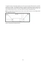
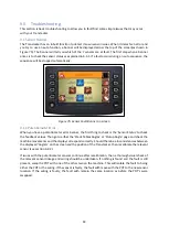
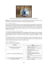
Figure 76: Potentiometer with centre spindle position in relation to cable exit
NOTE:
If you are changing the POT sensors, the flat edge on the centre spindle needs to be in line
cable exit on the sensor needs to remain as similar as possible (see Figure 76).
9.1.2 Inductive Switch Error
When you have an inductive switch error, the banner will only pop up when the
‘
Sensor Status
’
of the
sensor is blue. You will need to visually inspect the wiring harnesses and the sensors on the machine.
Should there be any damage to the sensor, particularly to the sensing face of the sensor, then the
sensor needs to be changed. Should the fault still be present, then contact the Service Department at
Big Bale Co. South Ltd.
9.2 Common Symptoms and their Cause
These table lists possible faults/adjustments that could happen to the Transtacker. Should you have
an
auto function fault that isn’t listed
, you can follow the relevant auto function sequence using the
software diagram in section 8 or alternatively contact the Service Department at Big Bale Co. South
Ltd.
To quickly find the fault, you can see the functions of the auto sequence in the top right-hand corner
of the screen (see section 5.2.5). once you
’
ve identified the function which
isn’t
completing, you can
identify the sensor and/or timer in question to resolve the issue.
9.2.1 Auto Pickup Issues
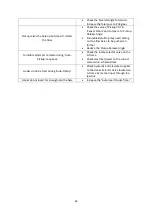
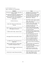
Table 11: Auto-Pickup troubleshooting
Symptom
Cause
The pickup tines enter the bale and
immediately withdraw
•
Check the
‘Pickup Release Angle’ is set
to approximately
≥
175
o
•
Check the calibration of the Pickup POT
using
‘
Sensor Status
’
The tines do not penetrate the bale enough
•
‘
Auto-Insert Tines Timer
’
needs
increasing
•
Can hold the joystick forward to
continue putting tines in further (see
section 5.3.3)
•
There are too many tines are in the tine
frames
The pickup
stops at the ‘Hold Angle’ when
‘
Auto-Stack
’
isn’t active
•
Check the Turntable Lift POT. The value
has to be
≤
1 degrees
Summary of Contents for Transtacker
Page 7: ...7 3 0 Machine Overview Figure 1 Transtacker Overview...
Page 43: ...43 Figure 59 Auto Settings Screen...
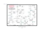
Page 57: ...57 8 1 Auto Pickup Sequence Figure 69 Auto Pickup Diagram...
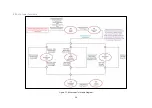
Page 58: ...58 8 2 Auto Stack Sequence both with and without tie Figure 70 Auto Stack Diagram...
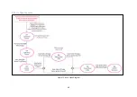
Page 59: ...59 8 3 Auto Lower Turntable Figure 71 Auto Lower Turntable Diagram...
Page 60: ...60 8 4 Auto Open Sequence Figure 72 Auto Open Diagram...
Page 61: ...61 8 5 Auto Tip Bed Down Sequence Figure 73 Auto Tip Bed Down Diagram...
Page 62: ...62 8 6 Road Mode Sequence Figure 74 Road Mode Diagram...


