54
7.0 Electrical and Hydraulic System
7.1 Electrical System
7.1.1 Fusing locations and functions
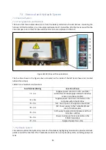
There is a 30A fuse located about 0.3m from the battery terminal in the cab harness. Assuming the
harness is fitted to battery, it can be easily
overlooked as it’s not
visible. All other fuses are within the
clear Perspex cover in the ECU Box and their functions are explained in Table 9.
Figure 68: ECU Box with Fuse locations
The fuse box shown in the figure above is located on the inside of the left hand chassis rail, located
behind the oil tank.
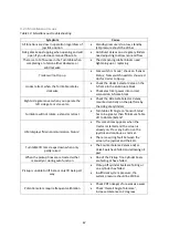
Table 9: Fuse Numbers and functions
Fuse Number/Rating
Function of Fuse
F1 - 5A
Supplies power into Pin 4 in the controller
within the ECU Box (supply used with inductive
sensors into the controller)
F2 - 15A
Supplies power into Pins 3-5 inclusive in the
controller within the ECU Box
F3
–
5A
Not used - Spare 12V supply to Valve Block
F4
–
5A
12V Power supply to the Turntable lift and
rotate Potentiometers
F5
–
5A
12V Supply to pickup Potentiometer and the 4
inductive switches
F6
–
5A
Power to all proportional solenoids on the
PVG32 Valve Block
F7
–
5A
Supply of power to E-stop
7.2 Hydraulic System
This section outlines the hydraulic system of a Transtacker, highlighting maintenance points and check
points around the machine. The Transtacker contains its own hydraulic system, including pump and
tank.
Summary of Contents for Transtacker
Page 7: ...7 3 0 Machine Overview Figure 1 Transtacker Overview...
Page 43: ...43 Figure 59 Auto Settings Screen...
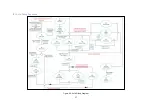
Page 57: ...57 8 1 Auto Pickup Sequence Figure 69 Auto Pickup Diagram...
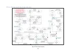
Page 58: ...58 8 2 Auto Stack Sequence both with and without tie Figure 70 Auto Stack Diagram...
Page 59: ...59 8 3 Auto Lower Turntable Figure 71 Auto Lower Turntable Diagram...
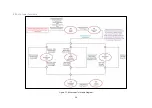
Page 60: ...60 8 4 Auto Open Sequence Figure 72 Auto Open Diagram...
Page 61: ...61 8 5 Auto Tip Bed Down Sequence Figure 73 Auto Tip Bed Down Diagram...
Page 62: ...62 8 6 Road Mode Sequence Figure 74 Road Mode Diagram...

