background image

37 


6.1.2 Pickup Height Plates for corresponding bale size 

The pickup is mounted on to the chassis by 2 vertical square posts that slide vertically in brackets on 
the chassis. The height of the pickup is dictated by pins and plates inserted through holes in the 2 
vertical square posts. 

The correct height  for the pickup is half way between the top of the bale and the top of the  fully 
lowered and retracted turntable. It follows that changing the height of the tractor drawbar will have 
an effect on the pickup height, though different heights of bales will have a more considerable effect 
on the pickup adjustment.  

To adjust the pickup height, proceed as follows: 

1.


Stop the machine on level flat ground, in a straight line. 

2.


Switch off the control system and the PTO to prevent the machine from being able to move.  

3.


Raise the pickup up off the stop plates using the tractor spool.  

Note

: Flow rate wants to be approx. 20% of max flow. 

4.


Pull the R clips out of the pins and move the pins and plates to the holes in vertical legs to 
achieve the position as described above. 

a.


NOTE

: The plates have two sets of holes and are off-centre so inverting the plates 

will give you a finer level of adjustment.  

5.


Return to the cab and lower the pickup onto the stop plates and put the spool in float.  


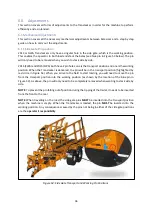
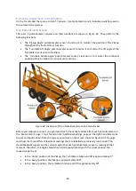
Figure 54: Position of Pickup Height Plates to protect Pickup Lift Cylinder 

NOTE:

 The plates CANNOT be proud of the top of the vertical legs (Figure 54). If the plates are proud 

of the  legs, the  plates will  cause  damage to the pickup lift  cylinders. 

If you’re picking up 1

.2x0.7m 

bales, you’ll find the pickup frame can rest on the chassi

s and remove the pickup height plates and 

pins all together.   

When entering and exiting gateways, you can raise the pickup off the stops to increase the ground 
clearance of machine. This may be of particular use if you have the Pickup Shoe lower than the bottom 
rail of the pickup (see 6.1.5 about for Pickup Shoe adjustment).   

Summary of Contents for Transtacker

Page 1: ...efore operating the machine It is the responsibility of the operator to read and understand the contents of this manual in full before operating the machine for the first time The Operators Manual mus...

Page 2: ...Bale Layout Symbols and Deletion 15 5 2 7 Bale Count Screen 16 NOTE The bale count only increments when the Retract Tines action is completed as part of the Auto Pickup cycle Therefore if the Auto Pic...

Page 3: ...32 5 4 6 Retrieving an erected Stack 33 6 0 Adjustments 36 6 1 Mechanical Adjustments 36 6 1 1 Side Gate Pins position 36 6 1 2 Pickup Height Plates for corresponding bale size 37 6 1 3 Forks bolting...

Page 4: ...uto Lower Turntable 59 8 4 Auto Open Sequence 60 8 5 Auto Tip Bed Down Sequence 61 8 6 Road Mode Sequence 62 9 0 Trouble Shooting 63 9 1 Sensor Banner 63 9 1 1 Potentiometer Error 63 9 1 2 Inductive S...

Page 5: ...uired it is necessary to quote the machine serial number This is located at the front right hand side of the machine on top of the drawbar front plate 1 3 Intended Use of the Machine The Big Bale Tran...

Page 6: ...Hydraulic requirement 1 double acting spool 2 3 Bale Sizes and quantity to be carried Table 3 Bale sizes and quantities Number of bales Transtacker can hold Bale size m Normal load With extra layer 0...

Page 7: ...7 3 0 Machine Overview Figure 1 Transtacker Overview...

Page 8: ...oving machinery WARNING Guidebar When the pickup Guidebar is in use there is a danger that it may be overlooked by the operator An indicator on the pickup latch signals to the operator that the Guideb...

Page 9: ...ses for controlling the pickup height The two pipes need to be connected as a pair Release the Transtacker handbrake as shown in the top right corner of Figure 1 which is under the front left of the c...

Page 10: ...onnector plugs into the male circular aluminium connector located on the tool post of the Transtacker 5 2 3 Joystick Functionality To operate functions refer to Table 4 to choose the function you wish...

Page 11: ...Close Left Gate Close Left Gate Right Close Right Gate Close Right Gate Middle Forward Auto Lower Turntable Retract Hooks Backward Open Rear Clamps Open Rear Clamps Left Retract Guide Bar Lower Turnta...

Page 12: ...ds The Entering Road Mode notice bar will appear at the top of the screen see Figure 5 To successfully enter Road Mode the PTO must be running and the trailer will close up ready to travel on the high...

Page 13: ...you will be met with the screensaver screen shown in Figure 7 To get to the work screen press any button on the joystick The screensaver will also reappear after a predetermined period of time defaul...

Page 14: ...ack Mode and when the Stack Mode symbol is shown the machine is in Field Mode The screen also gives you feedback during the an Auto sequence Figure 8 shows the Auto Stack with Tie symbol is highlighte...

Page 15: ...ason then it is possible to use the bottom left button on the screen to delete the cancelled layer This way the bale display will always correspond to the number of layers on the Transtacker The layer...

Page 16: ...hen these bales will not be counted on the bale count To return to work screen from this screen press the Enter button located on the bottom right of the screen 5 3 Loading bales onto your Transtacker...

Page 17: ...Open Left Gate Left Screen and Open Right Gate Right Screen 4 Move the joystick left and right to open the side gates Figure 13 a NOTE On the EWA and FWA the side gate pins have a lock position and w...

Page 18: ...y for use Figure 15 NOTE The forks will automatically retract during an Auto Stack sequence or when the Turntable is retracted and no additional operation is required The forks will automatically be f...

Page 19: ...ined below During the lowering of the pickup within the auto pickup sequence should you wish to push the bale further across the turntable wait until the pickup is approximately half way through lower...

Page 20: ...joystick forward and the pickup will lift the bale Figure 18 This function is proportional so the further forward you push the joystick the faster the pickup will raise a NOTE The hooks will automati...

Page 21: ...ick backwards to lower the pickup to its home position Figure 21 8 Repeat process from step 1 until Turntable is full 5 3 5 Auto Stack with Tie Operation Before operating the auto stack function ensur...

Page 22: ...the joystick left and right you can also close the gates while the auto stack function is operating 5 3 6 Auto Stack with No Tie Operation When building a stack the easiest way is to incorporate No Ti...

Page 23: ...s Once the Auto Stack is complete and the Auto Pickup symbol becomes brown then the sequence can be cancelled by pushing the joystick to either side While the Auto Stack is Active you can still open a...

Page 24: ...oystick forward momentarily to lift the turntable clear of the pickup and stops a NOTE Turntable lift POT sensor angle must be greater than setting Minimum Table Lift to Rotate Extend for Turntable to...

Page 25: ...Hold down the middle button and move the joystick right to extend the turntable further forward Figure 28 a NOTE IT IS THE OPERATOR S RESPONSIBILTY TO ENSURE TRANSTACKER MAINTAINS SAFE DISTANCE FROM T...

Page 26: ...Lower Stack Table 10 Hold down the middle button and move the joystick left to lower the turntable away from the bales to approx 45o Figure 32 Figure 33 Rotate Stack Table Anticlockwise 11 Hold down t...

Page 27: ...ill rotate it back to its home position if necessary before lowering it onto the turntable stops 5 3 10 Completing a Load At the rear of the trailer there is a sensor that detects when the trailer is...

Page 28: ...lural stacks it is recommended to use a tramline as a guide in order to get the stack in line 1 Press and hold to exit Road Mode and switch to Stack Mode if required 2 Manoeuvre the machine where you...

Page 29: ...ack Table 8 Keep the middle button held down and move the joystick left to lift the Turntable off the stack and to lower the Turntable to approximately 45 degrees Figure 39 Figure 40 Extend Stack Tabl...

Page 30: ...e off the lift assistor cylinders Figure 42 3 Reverse slowly until the you feel the trailer make contact with the existing stack Using the Transtacker mudguard as a reference pull forward approximatel...

Page 31: ...rd or hold down the bottom left button and pull the joystick backwards Figure 43 It s advised that if you use this function you need to be confident the stack is vertical and secure before releasing i...

Page 32: ...l to not overpower the rear clamps when releasing a stack Overpowering and opening the rear clamps excessively will cause the whole trailer to be pushed sideways and will cause excessive stress on the...

Page 33: ...it easier to retrieve a stack it is advised that stacks are tied together 1 If necessary exit Road Mode and put Transtacker into Stack Mode 2 Hold down either the top left button and push the joystick...

Page 34: ...before retracting the Turntable onto the top of the stack as this could cause damage to the Turntable Figure 49 Retract Stack Table 6 Continue to hold down the bottom right button and move the joysti...

Page 35: ...able to clamp the bales as intended Figure 52 Tip Bed Down 9 Push the joystick forward all the way until the platform is resting on the Stops Figure 52 10 Enter Road Mode to ensure safety of load befo...

Page 36: ...ition When the Transtacker is delivered the pin will be in the transport position highlighted by red circle in Figure 53 When you arrive to the field to start loading you will need to move the pin fro...

Page 37: ...actor spool Note Flow rate wants to be approx 20 of max flow 4 Pull the R clips out of the pins and move the pins and plates to the holes in vertical legs to achieve the position as described above a...

Page 38: ...Stop the PTO and bolt the forks down at the rear and tighten the bolts 8 Return to the tractor and re engage the PTO Select Field Mode Press the bottom right button and push the joystick forward to te...

Page 39: ...the pickup would not have pushed the bale far enough onto the turntable In this case you will need to slide the bar out of one hole The Turntable Stop should only need adjusting in the initial setup o...

Page 40: ...even over the length of the bale 6 3 Settings Explained This section explains the functions of all the settings Should you wish to adjust any setting this section explains the effects and the possible...

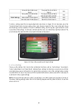
Page 41: ...Open Rear Clamps Speed The speed the rear clamps open 100 Guidebar Settings Manual Retract Guidebar Speed N A N A Manual Guidebar Extend Speed N A N A Hook Settings Manual Insert Hooks Speed The spee...

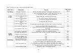
Page 42: ...decrease the value use the bottom right two buttons The plus increases the speed and the minus symbol decreases the speed Figure 58 Screen Showing Manual Clamp Settings 6 3 2 Auto Settings These are...

Page 43: ...43 Figure 59 Auto Settings Screen...

Page 44: ...the rear clamps close during auto functions 100 Auto Close Rear Clamps Timer Time Spent during the Auto Stack sequence when trailer is full to close the rear clamps Time spent closing the rear clamps...

Page 45: ...om the point when the Turntable begins to rotate 4s Auto Lower Stack Table Speed The maximum speed the Turntable will lower at during Auto Stack and ARTT Auto Return Turntable 85 Auto Raise Stack Tabl...

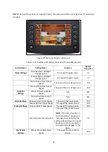
Page 46: ...ne In Table 8 all the settings their corresponding functions and the default setting value are listed Figure 60 Speed Angle Settings Screen Table 8 Speed Angle Settings Table of all settings Button Na...

Page 47: ...ing Auto Pickup while an Auto Stack sequence is happening 90 Degrees Pickup Release Angle The angle at which the pickup will stop raising and retract the tines 178 degrees Retract Guidebar Option Auto...

Page 48: ...potentiometers For example 90 2 degrees 2 Degrees Pickup Angle to Retract Hooks The angle at which the hooks will start to retract during the Auto Pickup sequence 10 Degrees Extra Layer Option Auto St...

Page 49: ...uto functions Figure 62 Locations of the 3 Potentiometers on the Transtacker Before you calibrate a sensor it is good practice to check the feedback from each potentiometer on the Sensor Status page T...

Page 50: ...f the screen there are instructions for you to follow With the PTO running you can follow the instructions The machine will move as will the graphics which replicate the real time movement of the Tran...

Page 51: ...ntil the Transtacker stops moving o NOTE The Transtacker should move in the opposite direction to step 1 5 Once the machine has stopped moving then press the button next to the floppy disc symbol 4th...

Page 52: ...4 sensors all have coloured dots next to them denoting their status The possible statuses are explained below A red dot shows the sensor is healthy and the sensor is not made A green dot shows the sen...

Page 53: ...om the sensor but no more than 6mm away To know the sensor is close enough to the LED the LED will be lit orange if the LED is flashing orange the sensor is at its limit of 8mm and needs to be adjuste...

Page 54: ...nd functions Fuse Number Rating Function of Fuse F1 5A Supplies power into Pin 4 in the controller within the ECU Box supply used with inductive sensors into the controller F2 15A Supplies power into...

Page 55: ...Filter mounted to the drawbar in front of the Valve Block The Return Filter should be changed every year and the Pressure Filter every other year 7 2 2 System Pressure The maximum hydraulic pressure o...

Page 56: ...hine is performing depending upon the text inside This example is Retracting Hooks Operator pushes joystick forward in field mode Red coloured text anywhere on the software diagrams requires input fro...

Page 57: ...57 8 1 Auto Pickup Sequence Figure 69 Auto Pickup Diagram...

Page 58: ...58 8 2 Auto Stack Sequence both with and without tie Figure 70 Auto Stack Diagram...

Page 59: ...59 8 3 Auto Lower Turntable Figure 71 Auto Lower Turntable Diagram...

Page 60: ...60 8 4 Auto Open Sequence Figure 72 Auto Open Diagram...

Page 61: ...61 8 5 Auto Tip Bed Down Sequence Figure 73 Auto Tip Bed Down Diagram...

Page 62: ...62 8 6 Road Mode Sequence Figure 74 Road Mode Diagram...

Page 63: ...error banner the first thing to check is the Sensor Status to check the feedback values Then go to either the Stack Tables Angles or Pickup Angle page and check the machine movements and the display...

Page 64: ...ion fault that isn t listed you can follow the relevant auto function sequence using the software diagram in section 8 or alternatively contact the Service Department at Big Bale Co South Ltd To quick...

Page 65: ...o be pushed on further Reduce the Pickup Release Angle Turntable attempts to rotate during Auto Pickup sequence Check the rotate selector valve on the A frame Check electrical power to the correct sol...

Page 66: ...centre more smoothly rather than being pushed and released to avoid cancelling the function The turntable lowers back down and rotates but won t lower onto the Stops Check the Turntable Rotate POT on...

Page 67: ...or vice versa Check the Side Gate Selector Valves mounted centrally on the platform by the side gate cylinders Turntable will not rotate extend or retract Turntable Lift Angle on Sensor Status has to...

Reviews: