


Table of Contents
1. Introduction
ORM0043_2
Modulating Controller Application Manual
Page 2
1.
Introduction
……………………………………………………
2
2.
Actuator
………………………………………………………….
3
2.1
Solenoid Setup .
…………………………………………..
3
2.2
Modulating Control
……………………………………
. 3
2.3
Dead Zones
…………………………………………………
3
2.4
Pulse Zones
…………………………………………………
4
2.5
Actuator Limits
……………………………………………
4
2.6
Hard Seating
……………………………………………….
4
2.7
Digital Override …………………………………………
.. 5
2.8
Manual Override
…………………………………………
5
2.9
Fault Override …………………………………………….
5
2.10
System Fault
……………………………………………….
5
2.11
Feedback Signal Fault
…………………………………
5
2.12
Command Signal Fault
………………………………
.. 5
2.13
Common Fault
……………………………………...
...... 5
3.
Pump Setup
……………………………………………………
6
3.1
Pump On Demand
………………………………………
6
3.2
Pump On Pressure
………………………………………
6
3.3
Accumulator Pressure Signal Fault
……………..
6
3.4
Pump Fault
…………………………………………………
7
3.5
Pump Overrun Fault
……………………………………
7
3.6
Low Oil Level
………………………………………………
7
3.7
High Oil Temperature
…………………………………
7
4.
Miscellaneous
…………………………………………………
8
4.1
Supply Pressure Monitoring ……………………….
8
4.2
Controller Access
………………………………………..
8
5.
Display
……………………………………………………………
9
5.1
Screen 1
……………………………………………………..
9
5.2
Screen 2
……………………………………………………..
10
6.
Appendix
………………………………………………………..
11
6.1
System Inputs
……………………………………………..
11
6.2
System Outputs
………………………………………….
12
6.3
System Values
…………………………………………….
13
6.4
System Times
……………………………………………..
14
6.5
HART Variables ……………………………………………
14
This manual provides instruction on the setup and
analysis of the modulating controller application.
Section 2 details specific actuator modules included
within the application and what settings should be
changed to affect actuator operation.
Section 3 details specific hydraulic pump modules
included within the application and what settings should
be changed to affect pump operation.
Section 4 details any further miscellaneous modules
included within the application and what settings should
be changed to affect controller operation.
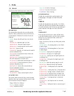
Section 5 details the information that can be displayed
on the main screen of the controller.
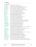
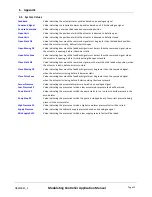
Section 6 is an appendix which lists all available settings
and values that can be changed on the controller.
For each section a combination of System Inputs,
Outputs, Values and Times will be referenced. The key
for the settings are as follows:
System Inputs
System Outputs
System Values
System
Times


