background image

Installation, Operation and Maintenance Manual

September 2019

MAN720_IMVS2000v2_IOM Rev. 6

Section 6: Configuration Parameters

Configuration Parameters

Section 6: Configuration Parameters

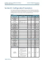
This section lists and describes the configuration parameters of the IMVS2000v2. For details about 
the mapping of the parameters on the Local Operator Interface, see 7. For details about the mapping 
of the parameters on the “Biffi-Assistant” SW tool (RS232 and Bluetooth), see [1]. For details about 
the mapping of the parameters on the Bus Interfaces see the relevant manuals.

Table 5. 

PARAMETERS OF THE “VIEW/SETUP MODE” MENU

PARAMETER NAME

DESCRIPTION

RANGE

DEFAULT 

VALUE

R/W 

(1)

AVAILABLE 

ON (2) (3)

Dev. Mfr

(Device Manufacturer)

Biffi

Biffi

R

Local, Serial, 

Bus

Dev. Name

(Device Name)

IMVS2000v2 IMVS2000v2

R

Local, Serial, 

Bus

Dev. Tag

(Device Tag Name)

It is the named used the Bluetooth 
connection.
The Bluetooth name is created as follows: 
“BIFFI”+16 cha “-IMVS."

16 characters

All “0”

R/W

Local, Serial, 

Bus

Dev. S.N.

(Device Serial Number)

20 characters

All “0”

R/W

Local, Serial, 

Bus

Dev. Date

(Device Date of Manufacturing)

01-01-2014
31-12-2099

01-01-2014 R/W

Local, 

Serial,Bus

SW L. Card.

(SW Logic Card revision)

xx.xx.xx

R

Local, Serial, 

Bus

SW D. Card.

(SW Display Card revision)

xx.xx.xx

R

Local, Serial, 

Bus

Act. Mfr

(Actuator Manufacturer)

12 characters

All “ “

R/W

Local, Serial, 

Bus

Act. Model

(Actuator Model)

20 characters

All “ “

R/W

Local, Serial, 

Bus

Act. Tag

(Actuator Tag Name)

20 characters

All “ “

R/W

Local, Serial, 

Bus

Act. S.N.

(Actuator Serial Number)

20 characters

All “ “

R/W

Local, Serial, 

Bus

Act. Pr. Size

(Actuator Pressure Size)

10 characters

All “ “

R/W

Local, Serial, 

Bus

Act. Date

(Actuator Date of Manufacturing)

01-01-2014
31-12-2099

01-01-2014 R/W

Local, Serial, 

Bus

Valve Mfr

(Valve Manufacturer)

12 characters

All “ “

R/W

Local, Serial, 

Bus

Valve Model

20 characters

All “ “

R/W

Local, Serial, 

Bus

Valve Tag

(Valve Tag Name)

20 characters

All “ “

R/W

Local, Serial, 

Bus

Valve S.N.

(Valve Serial Number)

20 characters

All “ “

R/W

Local, Serial, 

Bus

Valve Date

(Valve Date of Manufacturing)

01-01-2014
31-12-2099

01-01-2014 R/W

Local, Serial, 

Bus

Act. Mode

(Acting Mode)

”Single” must be set in case of:
• 

Single Acting actuator with 
single SOV.

• 

Single Acting actuator with 2 
SOVs in series or in parallel.

”Double” must be set in case of:
• 

Double Acting actuator with 
dual SOVs.

”Double-S” must be set in case of:
• 

Double Acting actuator with 
single SOV.

• 

Double Acting actuator with 2 
SOVs in series or in parallel.

See 6.2 for details. If change it can 
generate the CAL alarm (see 8).

Single, 

Double,

Double-S

Single

R/W

Local, Serial, 

Bus


39

Summary of Contents for IMVS2000v2

Page 1: ...Installation Operation and Maintenance Manual MAN720_IMVS2000v2_IOM Rev 6 September 2019 Biffi IMVS2000v2 Integrated Monitoring Valve System ...

Page 2: ......

Page 3: ...n Parts 9 4 3 Technical Specifications 12 4 4 Overall Dimensions 14 4 5 Options 14 Section 5 Working Principle and Detailed Description 5 1 Working Principle 15 5 1 1 Calibration 16 5 1 2 Signature 16 5 1 3 Opening and Closing FST External Source 17 5 1 4 PST 17 5 1 5 SOVs Test 18 5 1 6 Closing FST Details 20 5 1 7 Opening FST Details 21 5 1 8 PST and SOV TEST Details 22 5 2 Detailed Description 3...

Page 4: ...tion F Wiring Diagram 83 9 2 7 Configuration G Wiring Diagram 84 9 2 8 Configuration H Wiring Diagram 85 9 2 9 Hart Card Wiring Diagram 86 Section 10 INSTALLATION START UP 10 1 Installation in ambient with explosive dusts 88 10 2 Checks to be performed before installation 88 10 3 Preliminary operations 89 10 4 Mechanical Connections 90 10 4 1 Mounting IMVS2000v2 onto RP RPS type actuators 90 10 4 ...

Page 5: ...tallation Operation and Maintenance Manual Reference Documents Section 1 Reference Documents 1 MDE231 IMVS2000v2 Biffi Assistant User Manual 2 MDE232 HRT_IMVS2000v2 User Manual 3 MDE243 IMVS2000v2 MODBUS User Manual 1 Section 1 Reference Documents ...

Page 6: ...ring installation operation adjustment and maintenance of the machine Such risks lie entirely with the user Depending on the specific working conditions additional precautions may be requested Considering that Biffi Italia has no direct control over particular applications operation or maintenance conditions it is the operator s responsibility to comply with all applicable safety rules Please info...

Page 7: ...quivalent type 2 3 Terms and Conditions Biffi Italia guarantees each single product to be free from defects and to conform to current goods specifications The warranty period is one year from the date of installation by the first user or eighteen months from the date of shipment to the first user whichever occurs first No warranty is given for products which have been subject to improper storage i...

Page 8: ...lied only to demonstrate that the IMVS2000v2 does not adversely affect the execution of the safety function ESD by the superior SIS and does not contribute to the PFDav 2 6 CSA CSAus Certifications Details Canada Class I Division 1 Groups B C D T4 Class II Groups E F and G Class III Ex db ia IIC T4 Gb Ex tb IIIC T135 C Db Integrated Monitoring Valve System Model IMVS2000v2 Ambient temperature rang...

Page 9: ...tacted for guidance and information on the dimensions of the flameproof joints 2 The user shall be aware that all external fasteners on which the flameproof enclosure depends are stainless steel socket head cap screws class A4 grade 70 3 Equipment is only to be installed by manufacturer trained personnel 4 The scope of this approval does not include any safety related function performance or relia...

Page 10: ...2 No 30 M1986 2016 Explosion Proof Enclosures for Use in Class I Hazardous Locations CAN CSA C22 2 No 25 1966 R2014 Enclosures for Use in Class II Groups E F and G Hazardous Locations CAN CSA C22 2 No 157 Intrinsically safe and non incendive equipment or use in Hazardous Locations ANSI ISA 60079 0 Ed 6 Electrical Apparatus for Explosive Gas Atmospheres Part 0 Equipment General Requirements ANSI IS...

Page 11: ... by an individual certificate In order to maintain these characteristics until the IMVS2000v2 is installed on site proper attention must be observed for preservation during the storage period The standard plastic plugs used to protect the cable entries during the transport are not weatherproof they just prevent the entry of undesired objects during transport during the storage it is recommended to...

Page 12: ...ed to are the installation on all type of actuators driven pneumatically or hydraulically for ON OFF ESD applications Different versions are available for single or double acting actuators actuators pneumatically or hydraulically operated rotary or linear actuators direct installation on actuator 4 1 1 Main Features In the following section the main features of the IMVS2000v2 are listed For additi...

Page 13: ...isolated solid state relay Digital Outputs DO OPEN CLOSE COMMON FAILURE ALARM PST IN PROGRESS PST PASSED PST FAILED AUTO DIAGNOSTIC The IMVS2000v2 monitors the status of its internal sensors pressure and position ADDITIONAL BUS CARDS The IMVS2000v2 has the possibility to use one of the following optional Bus Card HART Card HART 7 MODBUS Card MODBUS RTU 4 2 Identification of the Main Parts In this ...

Page 14: ...covers are made in Stainless Steel Class A4 grade 70 with a minimum yield strength 450 N mm The shaft which transmits the movement from the valve to the internal position sensor is supported by a bush mounted on the sensors manifold and blocked on the external diameter with LOCTITE 638 or equivalent The various explosion proof joint surfaces can be lubricated with Aeroshell Grease 10 ...

Page 15: ...N720_IMVS2000v2_IOM Rev 6 Section 4 Device Description Device Description Figure 2 Pos Description 1 Position Sensor Assembly 2 Barrier Card 3 Display Logic Cable 4 Pressure Sensor 5 Position Indicator 6 Base Power Card 7 Bus Card OPT 8 Display Card 9 Logic Card 11 ...

Page 16: ...ice Current Consumption min 2 0 mA max 11 mA Galvanic Insulation from Logic YES Galvanic Insulation from others DIs YES Digital Outputs SPST solid state dry contact Maximum allowed Voltage up to 57 6 Vdc up to 35 Vdc for CSA CSAus device Maximum allowed Current up to 0 5 A Galvanic Insulation from Logic Yes Galvanic Insulation from others DOs Yes Pressure Sensors Range Option 1 up to 10 barg 145 p...

Page 17: ...sulation from Logic Yes 4 20 mA Analog Output HART optional card Feedback Signal Pressure or Position Output Current Range 4 20 mA Maximum Load cable resistor 300 ohm External Power Supply Voltage 21 6 26 4Vdc max 21 mA Galvanic Insulation from Logic Yes Notes Consult Factory for availability Consult Factory for applications over 345 barg Contact Biffi for the availability of applications that do ...

Page 18: ...019 Installation Operation and Maintenance Manual MAN720_IMVS2000v2_IOM Rev 6 Section 4 Device Description Device Description 4 4 Overall Dimensions Figure 3 4 5 Options See Section 14 for the available options 14 ...

Page 19: ...solutevalueofthedifferencebetweenPressure1andPressure2 It is possible to set tolerances on time pressure and position of both FST and PST During the commissioning procedure see 10 7 the IMVS2000v2 stores the ideal opening FST and closing FST Baseline Signature the ideal PST Baseline PST The further FSTs Maintenance Signature Opening FST or Closing FST are compared with the Baseline Signature and f...

Page 20: ...e Signature Maintenance Signature To performe the Baseline Signature and the Maintenance Signature the IMVS2000v2 must be correctly connected and configured and it must be able to control the valve actuator system The Baseline Signature can be performed only if a Calibration is already successfully executed The Maintenance Signature can be performed only if a Baseline Signature is already successf...

Page 21: ...2 continuously monitors the position of the valve actuator If a complete Opening FST or a complete Closing FST is performed without using the IMVS i e external SOV not controlled by the IMVS2000v2 the device records the graph of the FST The data of this kind of FST are not compared with the ones of the Baseline Signature It is possible to store the FST data only if a Baseline Signature is already ...

Page 22: ...res and position stable valveinits normal workingposition e g Openpositionfora failtoclose actuator 5 1 5 SOVs Test The IMVS2000v2 can control up two external SOVs with independent and isolated circuits The IMVS2000v2 can perform the SOV test to check the SOV integrity if A single SOV is present Two SOVs are connected in series See 6 2 for details The SOV test consists of managing one or two SOVs ...

Page 23: ...ee Errore L origine riferimento non è stata trovata for details 3 Configuration Z Act Mode Single or Double S SOVs Qty Simplex PST Ser SOVs One Pr S 1 2 None PST En No PST Pos 0 0 PST Pres 0 PST Time 0 Al PSA En No 4 Configuration T Act Mode Single or Double S SOVs Qty Series PST Ser SOVs Both Pr S 1 2 None PST En No PST Pos 0 0 PST Pres 0 PST Time 0 Al PSA En No Al PSB En No The SOV TEST can be p...

Page 24: ...ssure is expressed as the absolute value of the difference between the Pressure 1 pressure sensor S1 and the Pressure 2 pressure sensor S2 Considering that Op Br Pos and Cl Br Pos are fixed to 3 Closing Break Time time to go from Open Position to 97 Closing Break Pressure pressure measured at 97 Closing Travel Time time to go from 97 to 3 Ifthestartingpositionisnothigherthan97 theClosingBreakTime ...

Page 25: ...the Pressure 1 pressure sensor S1 and the Pressure 2 pressure sensor S2 Considering that Op Br Pos and Cl Br Pos are fixed to 3 Opening Break Time time to go from Closed Position to 3 Opening Break Pressure pressure measured at 3 Opening Travel Time time to go from 3 to 97 Ifthestartingpositionisnotlowerthan3 theClosingBreakTime theClosingTravelTimeandtheClosing BreakPressurearesetto0 Ifattheendof...

Page 26: ... Pos are fixed to 3 PST Break Time time to go from Open Position to 97 PST Break Pressure pressure measured at 97 PST Travel Time time to go from 97 to 97 passing for the setpoint If the starting position is not higher than 97 the PST Break Time the PST Travel Time and the PST Break Pressure are set to 0 If at the end of the PST the position is lower than 97 the PST Travel Time is set to 0 The PSC...

Page 27: ... PST Break Time the PST Travel Time and the PST Break Pressure are set to 0 If at the end of the PST the position is higher than 3 the PST Travel Time is set to 0 The PSCT alarm if enabled is generated see Sections 5 2 7 and 8 for details The PST Break Time the PST Travel Time and the PST Break Pressure of the Baseline PST are compared to the ones of the last Manual PST and if they do not respect ...

Page 28: ... and the SOVA is used to get the setpoint of the PST After each performed PST the IMVS2000v2 reverses the solenoid valve test sequence It is possible to configure the IMVS2000v2 to test the SOVs individually PST Ser SOVS One During the first PST the SOVA is used to get the setpoint of the PST and the SOVB is not tested During the next PST the SOVB is used to get the setpoint of the PST and the SOV...

Page 29: ...hese commands the SOV A is used PST St doesn t describe the result of the last SOV B TEST If the command is received but Cal Status Passed or Base S St Passed or B PST St Passed or Pr S 1 2 None or Then The command is not executed The PSB Alarm is activated if enabled The graph is not stored If the command is received but Cal Status Passed and CAL Alarm is active or POS Alarm is active or HSP Alar...

Page 30: ... Pres 0 PST Time 0 Figure 10 During the SOV TEST the SOV A is briefly used for a short period of time to generate a pressure drop inside the cylinder detected by pressure sensor without generating the actuator s movement The SOV TEST Time is automatically set by the IMVS2000v2 The SOV A TEST is executed only on to the SOV A To perform the SOV A TEST the following commands must be successfully exec...

Page 31: ...ne SOV A Test is executed all previous SOV A TEST are cleared The SOV A Test can be executed only if the Baseline SOV A Test is successfully executed The SOV A Test can be performed by using Manual PST command or DI PST CONTROL PST St describes the result of the last SOV A TEST M PST Date and M PST Time indicate the date and the time of the last SOV A Test If the command is received but Cal Status...

Page 32: ...he value Passed M PST Date and M PST Time assume the current date and time values The PSA Alarm is cleared The DO PST PASSED contact is closed The DO PST FAILED contact is opened A new graph is stored the Status is Passed 5 1 8 4 SOV A and SOV B TEST Details Available from Logic Card FW Rev 1 00 01 The figure below shows an example of SOVs TEST on SOV A and SOV B on a system of two SOVs in series ...

Page 33: ... SOV A SOV B Test SOV A SOV B Test The Baseline SOV A SOV B Test can be performed by using Baseline PST command B PST St describes the result of the last Baseline SOV A SOV B Test B PST Date and B PST Time indicate the date and the time of the last Baseline SOV A SOV B Test If the Baseline SOV A SOV B Test command is received but Cal Status Passed or Base S St Passed or Pr S 1 2 None or Al PSA En ...

Page 34: ...is active or LSP Alarm is active or The start position is not valid Then The command is not executed PST St assumes the value Failed M PST Date and M PST Time assume the current date and time values PSA Alarm and PSB Alarm are activated The DO PST PASSED contact is opened The DO PST FAILED contact is closed The graph is not stored If a problem is verified during the SOV A SOV B TEST execution PST ...

Page 35: ...n Two push buttons DOWN UP are used to move into the menu and changing the value of the parameters while the third ENTER is used to enter the selected information and for moving between the sub menus and for waking up the IMVS2000v2 The configuration operations are protected by password The operator can access the Setup Mode menu and change the parameters only after entering the appropriate passwo...

Page 36: ...A CTRL active and Act Mode Double Terminals11 10 0 Volts Terminals 11 9 power supply applied on terminals 6 5 This DI is used to define the Position Request see the Posi tion Request Table The command associated to this DI is considered active when a correct voltage is applied on its terminals Push to run SOLENOID B CONTROL SOV B CTRL 21 22 Digital Input Itisusedfor controllingthe RELAYBcontacttha...

Page 37: ...uble if the SOV A CMD is active the SOV B CMD is automatically ignored This command can be performed only if the Manual PST command is available see 6 for details The change of status from not active to active is used when the DI is associated to the SOV TEST command 5 2 2 2 Position Request Table The following table shows how the Digital Inputs according to different settings determines the Posit...

Page 38: ...gle or Double S OP Parallel Not Active Not Active 100 Double Active Not Active 100 Double Not Active Active 0 Double Not Active Not Active Last Position Request Double Active Active 100 5 2 3 Digital Output The IMVS2000v2 is provided with 6 Digital Outputs DO OPEN CLOSED COMMON FAILURE ALARM PST IN PROGRESS PST PASSED PST FAILED Each DO is isolated from the other ones and can work with the followi...

Page 39: ...ed Not Done Conf Err contact open PST Status Progress contact closed It is updated at the end of each PST or SOV Test See 6 for details PST FAILED 35 36 Digital Output It is a solid state dry contact that depends on the value of PST Status PST Status Passed contact open PST Status Failed Conf Err contact closed PST Status Not Done contact open PST Status Progress contact closed It is updated at th...

Page 40: ...ms General Diagnostic Alarms Auto diagnostic Alarms CAL alarm The PST Alarms deal with the results of the PST They are acyclic alarm that can be activated at the end of a PST execution They are de activated by a power on reset or by the Reset Alarms command The FST Alarms deal with the results of the FST They are acyclic alarm that can be activated at the end of a FST execution They are de activat...

Page 41: ...he pressure sensor 2 is present and enabled if the process pressure sensor is present and enabled The samples period is a multiple of 5ms The time length of each graph is a multiple of 1 75 seconds The time length of each graph is automatically calculated by the IMVS2000v2 The time length of the Opening FST is determined by the parameter Opening Maximum Time that is automatically set equal to the ...

Page 42: ...ait for the Closing Maximum Time before Opening the graph could have less than 351 samples The Digital Input FST Graphs can be stored only if Baseline Signature is already successfully performed 5 2 8 2 External Source FST Graphs The IMVS2000v2 can store the graphs of the FST generated by external sources i e SOVs not controlled by the IMVS2000v2 The FST is memorized only if the position changes a...

Page 43: ...evision xx xx xx R Local Serial Bus SW D Card SW Display Card revision xx xx xx R Local Serial Bus Act Mfr Actuator Manufacturer 12 characters All R W Local Serial Bus Act Model Actuator Model 20 characters All R W Local Serial Bus Act Tag Actuator Tag Name 20 characters All R W Local Serial Bus Act S N Actuator Serial Number 20 characters All R W Local Serial Bus Act Pr Size Actuator Pressure Siz...

Page 44: ...ssure range of the processpressure sensor None Processpressure sensor notpresent Itispressure range of the processpressure sensor Thepressuremeasurementunit bar or psi is determinedbythe settingof the Pres M U parameter None 10 20 50 100 200 400 bar None 145 290 725 1450 2900 5800 psi None R Local Serial Bus Set Pr 1 2 Set Pressure 1 2 This command is used to set the pressure range of the pressure...

Page 45: ...ctsthe duration of the Open ingFSTtime window Itissuggestedtoperform anew Baseline Signature after changingthis parameter tobetter compare the nextSignatures andFSTs 0 200 20 R W Local Serial Bus Cl Time Closing Time Hyster esis Itdefinesthe tolerance for the generationof the followingalarms SCBT FCBT SCTTandFCTT SeeSection 8for details Thisparameter affectsthe duration of the Closing FSTtimewindo...

Page 46: ...it s possible to perform the SOV Test See Section 5 1 6 for details Yes No Yes R W Local Serial Bus PST Set PST Setpoint It defines the position to be reached during the PST It must be considered that 100 cor responds to the fully open and 0 to the fully closed position This parameter affects the duration of the PST time window It is recommended to perform a new Baseline PST after changing this pa...

Page 47: ... 00 R W Local Serial Bus Calibration Cmd Itisthecommandfor performingthe device Calibration See Section 5 1 1for details The Calibration deletesallthe storedBaseline and Maintenance FSTsandallthe storedBaseline and ManualPSTs Start C Local Serial Bus Cal Date Calibration Date Itisthedate of the lastperformedCalibration 01 01 2014 31 12 2099 01 01 2014 R Local Serial Bus Cal Time Calibration Time I...

Page 48: ...ase S St Baseline Signature Status It is the status of the last Baseline Signature Not Done no Baseline Signature is performed yet Progress during the execution of a Baseline Signature Failed some errors occur during the last Baseline Signature Passed Baseline Signature successfully performed Conf_Err the command is not performed due to wrong configuration or Pos Req not aligned with Position or i...

Page 49: ...s not performed due to wrong configuration or Pos Req not aligned with Position or if the command is not available Signatures En or Base S Status or Op Max time 0 or Cl Max Time 0 CAL or POS alarms active etc Otherwise it is Passed Failed is squelched by Conf Err See 8 for details It is set to Not Done after every Calibration or Baseline Sign Not Done Passed Failed Prog ress Conf_Err Not Done R Lo...

Page 50: ...ee Section 5 2 8 for details 0 1000 0 sec 0 sec R Local Serial Bus B Op T T Baseline Opening Travel Time It is the time measured during the Baseline Signature Opening FST that occurred for go ing from the Cl Break Pos to the 100 Op Break Pos See Section 5 1 8 for details 0 1000 0 sec 0 sec R Local Serial Bus M Op T T Maintenance Opening Travel Time It is the time measured during the last required ...

Page 51: ... and Digital Input FST with M FST Alr En No See Section 5 2 8 for details 0 1000 0 sec 0 sec R Local Serial Bus B Cl B P Baseline Closing Break Pressure It is the pressure measured during the Baseline Signature Closing FST when the position reaches 100 Op Break Pos See Section 5 1 6 for details If Act Mode Single this pressure value is made by the absolute value of the difference between Pressure ...

Page 52: ...seline Signature is performed and that the PST Time and PST Set parameters are set See 5 2 8 for details This parameter must be modified only if strictly necessary by expert users It can affect the operation of the device 1 7 2000 sec PST Cal Time R W Local Serial Bus B PST St Baseline PST Status It is the status of the last Baseline PST or Base line SOV Test Not Done no Baseline PST or Baseline S...

Page 53: ...Req not aligned with Position or CAL or POS or HSP or LSP alarms are active Otherwise it is Passed Failed is squelched by Conf Err See 5 1 5 for details It is set to Not Done after every Calibration Baseline Signature or Baseline PST PST St PST Status Not Done Passed Failed Progress Conf_Err R Local Serial Bus M PST Date Manual PST Time It is the date of the last performed Manual PST or SOV A Test...

Page 54: ...k Pos See Section 5 1 9 for details 0 1000 0 sec 0 sec R Local Serial Bus M PST B T Manual PST Break Time If Fail Act CL It is the time measured during the last Manual PST that occurred for going from the Starting Open Position to the 100 Op Break Pos See Section 5 1 9 for details If Fail Act OP It is the time measured during the last Manual PST that occurred for going from the Starting Closed Pos...

Page 55: ...y the RTC of the IMVS2000v2 01 01 2014 31 12 2099 actual R W Local Serial Bus Time It is the time hh mm ss updated by the RTC of the IMVS2000v2 00 00 00 23 59 59 actual R W Local Serial Bus N M Date Next Maintenance Date It is date used for generating the MNT alarm See Section 8 for details 01 01 2014 31 12 2099 01 01 2014 R W Local Serial Bus RTC Adjust RTC Adjust It is the number of seconds to a...

Page 56: ...ed and associated to the PST St and to the CFA St Set as ALR it is enabled and it is associated to the PST St but not to the CFA St See Sections 5 2 7 8 and 5 2 3 for details CFA ALR No CFA R W Local Serial Bus Al PSFT En Alarm PSFT Enabled Set as No it is disabled Set as CFA it is enabled and associated to the PST St and to the CFA St Set as ALR it is enabled and it is associated to the PST St bu...

Page 57: ... 2 3 for details CFA ALR No ALR R W Local Serial Bus Al CPOS En Alarm CPOS Enabled Set as No it is disabled Set as CFA it is enabled and associated to the CFA St Set as ALR it is enabled but not associated to the CFA St See Sections 5 2 7 8 and 5 2 3 for details CFA ALR No ALR R W Local Serial Bus Al LSP En Alarm LSP Enabled Set as No it is disabled Set as CFA it is enabled and associated to the C...

Page 58: ...t associated to the CFA St See Sections 5 2 7 8 and 5 2 3 for details CFA ALR No CFA R W Local Serial Bus Al SOTT En Alarm SOTT Enabled Set as No it is disabled Set as CFA it is enabled and associated to the CFA St Set as ALR it is enabled but not associated to the CFA St See Sections 5 2 7 8 and 5 2 3 for details CFA ALR No CFA R W Local Serial Bus Al FOTT En Alarm FOTT Enabled Set as No it is di...

Page 59: ...See Sections 5 2 7 8 and 5 2 3 for details CFA ALR No CFA R W Local Serial Bus Al PS1 En Alarm PS1 Enabled Set as No it is disabled Set as CFA it is enabled and associated to the CFA St Set as ALR it is enabled but not associated to the CFA St See Sections 5 2 7 8 and 5 2 3 for details CFA ALR No CFA R W Local Serial Bus Al PS2 En Alarm PS2 Enabled Set as No it is disabled Set as CFA it is enabled...

Page 60: ...e None no bus card present None HART MOD NONE R W Local Serial Bus Blue En Bluetooth Enabled If set as Yes the Bluetooth Interface is enabled Yes No Yes R W Local Change User PWD Change User Password It is the Password of the Local Operator Interface for logging in as User It is possible to set the new value when logged in as User The new password is active the old one is no longer valid after the...

Page 61: ...Local Serial Bus Graph ID Itdeterminesthe FSTID GraphType FST orPSTID GraphType PST of graphtostore throughthe Store Graph command 1 50 1 R W Local Serial Bus Slot Address Itdeterminesthe memoryaddresswhere the graphwillbe storedthroughthe Store Graph command 1 20 1 R W Local Serial Bus Store Graph Itstoresthe selected GraphType and Graph ID graphtothe setaddress SlotAddress Start C Local Serial B...

Page 62: ...the Pressure of the pressure sensor 2 It is applicable only if the pressure sensor 2 is present and enabled Act Mode Double or Pr 2 En Yes 0 400 bar 0 5800 psi actual R Local Serial Bus Proc Pres Process Pressure It is the value of the Pressure of the process pressure sensor It is applicable only if the process pressure sensor is present and enabled Proc S None 0 400 bar 0 5800 psi actual R Local ...

Page 63: ...Vs Actuator Type Single Simplex One Single Acting with one SOV Double S Simplex One Double Acting with one SOV Single Series One or Both Or Single Simplex Both Single Acting with two SOVs in series Double S Series One or Both Or Double S Simplex Both Double Acting with two SOVs in series Single Parallel NA Single Acting with two SOVs in parallel Double S Parallel NA Double ActingwithtwoSOVsinparal...

Page 64: ... bu on DOWN push bu on Two push buttons DOWN UP are used to move into the menu and for changing the value of the parameters while the third SELECT is used to enter the selected information and for moving between the sub menus and for waking up the IMVS2000v2 when only the Battery Pack Power Supply is present The Local Operator Interface is organized in four different main Menus Normal Mode Menu se...

Page 65: ...ay screens which are available without any password and can give some general pieces of information Figure 13 DOWN UP DOWN UP DOWN UP Login Menu Login Menu Login Menu SELECT UP or DOWN SELECT SELECT SELECT 100 0 Position 100 0 Pos Req 100 0 Alarms 0 Pressure 1 50 0 bar Pressure 2 0 0 bar Proc Pres 100 0 bar Date 25 12 2014 Time 20 30 2 Minutes without pressing any buttons First Display Screen afte...

Page 66: ...re reserved for Biffi Service and Production Figure 14 Select User Observer Select User Factory Select User User Select User VAC DOWN UP DOWN UP DOWN DOWN UP UP and DOWN to scroll the characters ENTER to confirm the selection and to pass to the next character of the password ENTER View Setup Mode Menu Wrong Password Correct Password PASSWORD 00000000 CORRECT PASSWORD PRESS ENTER TO CONTINUE WRONG ...

Page 67: ...ows the position of each available parameter of these menus To help reading the View Graph a different color is associated to the different menu entries Table 8 Menu and Sub Menu Exit of Menu and Sub Menu Available Parameter Available Command Calibration Available Command Parameter for VAC only for Biffi use only Unavailable Command Parameter for Biffi use only View Mode Menu Setup Mode Menu Exit ...

Page 68: ...Proc S Set Pr 1 2 Set Proc RL A Cmd RL B Cmd FST Settings Exit FST Settings Sign En Op Pos Cl Pos Op Time Cl Time FST Pr H Pr Lim L Pr Lim H Proc L L Proc L FST Cyc L FST Cyc C FST Ab C PST Settings Exit PST Settings PST En PST Set PST Pos PST Pr PST Time PST Ser SOVs PST Cyc L PST Cyc C PST Ab C A PST En A PST Per A PST Date A PST Time Calibration Exit Calibration Calibration Cmd Cal Date Cal Tim...

Page 69: ... Cl Status Mnt S St M S Date M S Time FST Stored FST ID FST Info FST Run Times Exit FST Run Times B Op B T M Op B T B Op T T M Op T T B Op B P M Op B P B Cl B T M Cl B T B Cl T T M Cl T T B Cl B P M Cl B P PST Results Settings Exit PST Results Base PST Cmd Manual PST Cmd PST Set PST Cal T PST Max T B PST St B PST Date B PST Time PST St M PST Date M PST Time PST Stored PST ID PST Info PST Run Times...

Page 70: ...Alarms Enabled Exit Alarms Enabled Al PSCL En Al PSCT En Al PSSB En Al PSFB En Al PSST En Al PSFT En Al PSSP En Al PSSR En Al PSLB En Al PSHB En Al PSNM En Al PSA En Al PSB En Al SISA En Al SISB En Al OPOS En Al CPOS En Al LSP En Al HSP En Al LPP En Al HPP En Al OPNM En Al CLNM En Al OPCT En Al CLCT En Al FSCL En Al SOBT En Al FOBT En Al SOTT En Al FOTT En Al SCBT En Al FCBT En Al SCTT En Al FCTT ...

Page 71: ...FST Al En Sensors Calibration Bus Factory Settings Exit Factory Settings Pressure Calib Memory Check AO Calibration Digital Inputs Exit Digital Inputs DI_SOVA St DI_SOVB St DI_PST St DI_SIS_A St DI_SIS_B St Check DOs Restore Defaults Stored Graphs Exit Stored Graphs Graph Type Graph ID Slot Address Store Graph Clear Slots Graphs Info Menu available only if a bus card is present See the manual dedi...

Page 72: ... to enter and exit the Menus and the Sub menus pressed on Menus and the Sub menus and on Exits of Menus and Sub Menus to select a parameter pressed the first time on Parameter to set the value of a parameter pressed on Parameter value after setting the new value to launch a command command pressed on Command After pressing the SELECT push button to set a parameter even if the value is not changed ...

Page 73: ... 0 Reset Alarms command Power on Reset Calibration Baseline Signature Baseline PST PST Slow Travel Time PSST Last Manual PST Travel Time is slower than the Baseline PST Travel Time by more than PST Time Hysteresis M PST T T B PST T T 1 PST Time 100 A new PST without the above condition resets this alarm Al PSST En No M PST T T 0 Reset Alarms command Power on Reset Calibration Baseline Signature Ba...

Page 74: ... with the SOV B test or a SOV A TEST or a SOV A SOV B TEST is performed See Sections 5 1 6 and 5 1 9 for details Pr S 1 2 None Act Mode Double SOVs Qty Series PST Ser SOVs One Al PSA En No Reset Alarms command Power on Reset Calibration Baseline Signature PST SOV B PSB If SOVs Qty Series The test of the SOVB during the PST does not cause a variation of the pressure It is automatically reset when t...

Page 75: ...s sure Limit L Proc Lim Actual Process Pressure L Proc Lim It is cyclically check period 30 seconds The check is interrupted during Calibration Signatures and PST executions Starting from Logic Card FW Revision 1 00 01 if HSP is active the PST is not executed Proc S None Al LPP En No Reset Alarms command Power on Reset High Process Pressure HPP The actual process pressure is greater than the High ...

Page 76: ... SCBT Last Maintenance ClosingBreakTime isslower thanthe Baseline ClosingBreakTime bymore than ClosingTime Hysteresis M Cl B T B Cl B T 1 Cl Time 100 AnewClosingFST withoutthe above condition resetsthisalarm Al SCBT En No M Cl B T 0 Reset Alarms command Power on Reset Calibration Baseline Signature Fast Close Break Time FCBT Last Maintenance ClosingBreakTime isfaster thanthe Baseline ClosingBreakT...

Page 77: ... S None Al PPS En No Reset Alarms command Power on Reset Position Sensor POS Failureof the PositionSensor Itiscyclicallycheck period 5seconds Reset Alarms command Power on Reset Bus Card BUS Internalcommunicationproblemswiththe buscard Itiscyclicallycheck period 30seconds Al BUS En No Reset Alarms command Power on Reset Maintenance MNT TheactualDate isgreater thanthe NextMaintenance Date NextMntDa...

Page 78: ...iptions Section 9 Wiring Diagrams Signals Description 9 1 Signals Description 9 1 1 Standard Signals Figure 15 CN20 for cable connection with Display Card Terminals 25 37 Logic Card Terminals 1 24 Base Power Card Thepreviousfigureshowsthestandardterminals withoutoptionalcards oftheIMVS2000v2 ThetablebelowdescribesthesignalsofthestandardterminalsoftheIMVS2000v2 74 ...

Page 79: ...SOVB 16 SOV B NC If used it must be connected to the positive terminal of the SOVB see Section 9 2 for details 17 SOV B NO If used it must be connected to the positive terminal of the SOVB see Section 9 2 for details 18 SOVB It must be connected to negative terminal of the SOVB see Section 9 2 for details It is internally connected to SIS B Digital Inputs 19 SOLENOID A CONTROL It is used for contr...

Page 80: ...8 41 HART Card The previous figure shows the terminals of the IMVS2000v2 HART Card The table below describes the signals of the of the HART Card terminals for details see 2 Table 11 Type Signal Name Description HART 38 HART_1 Hart 4 20 mA loop signal 39 HART_2 Hart 4 20 mA loop signal SHIELD 40 SHIELD Available connection for the cable Shield It is connected to the Protection Earth through a 2 2nF...

Page 81: ...rminals of the IMVS2000v2 MODBUS Card The table below describes the signals of the of the MODBUS Card terminals for details see 3 Table 12 Type Signal Name Description MODBUS 42 45 MODBUS B Modbus data line B 43 46 MODBUS A Modbus data line A 44 47 MODBUS R Modbus Reference line SHIELD 48 SHIELD Available connection for the cable Shield It is connected to the Protection Earth through a 2 2nF 4KV c...

Page 82: ...ing Diagrams SIgnals Description Wiring Diagrams Signals Descriptions 9 2 Wiring Diagrams 9 2 1 Configuration A Wiring Diagram Figure 18 Mandatory Connections MAIN SUPPLY terminals 3 4 SIS A SUPPLY terminals 5 6 SOVA terminals 9 11 All the other connections are optional see Section 9 1 1 for details 78 ...

Page 83: ...ms SIgnals Description Wiring Diagrams Signals Descriptions 9 2 2 Configuration B Wiring Diagram Figure 19 Mandatory Connections MAIN SUPPLY terminals 5 6 SOVA terminals 9 11 Recommended Connections SOLENOID A CONTROL terminals 19 20 All the other connections are optional see Section Section 9 1 1 for details 79 ...

Page 84: ...gnals Description Wiring Diagrams Signals Descriptions 9 2 3 Configuration C Wiring Diagram Figure 20 Mandatory Connections MAIN SUPPLY terminals 3 4 SIS A SUPPLY terminals 5 6 SIS B SUPPLY terminals 12 13 SOVA terminals 9 11 SOVB terminals 16 18 All the other connections are optional see Section 9 1 1 for details 80 ...

Page 85: ...iring Diagrams Signals Descriptions 9 2 4 Configuration D Wiring Diagram Figure 21 Mandatory Connections MAIN SUPPLY terminals 5 6 SOVA terminals 9 11 SOVB terminals 16 18 Recommended Connections SOLENOID A CONTROL terminals 19 20 SOLENOID B CONTROL terminals 21 22 All the other connections are optional see Section 9 1 1 for details 81 ...

Page 86: ...s Signals Descriptions 9 2 5 Configuration E Wiring Diagram Figure 22 Mandatory Connections MAIN SUPPLY terminals 3 4 SIS A SUPPLY terminals 5 6 SOVA terminals 9 11 SOVB terminals 16 18 Recommended Connections SOLENOID A CONTROL terminals 19 20 SOLENOID B CONTROL terminals 21 22 All the other connections are optional see Section 9 1 1 for details 82 ...

Page 87: ...iring Diagrams Signals Descriptions 9 2 6 Configuration F Wiring Diagram Figure 23 Mandatory Connections MAIN SUPPLY terminals 5 6 SOVA terminals 9 11 SOVB terminals 16 18 Recommended Connections SOLENOID A CONTROL terminals 19 20 SOLENOID B CONTROL terminals 21 22 All the other connections are optional see Section 9 1 1 for details 83 ...

Page 88: ..._IOM Rev 6 Section 9 Wiring Diagrams SIgnals Description Wiring Diagrams Signals Descriptions 9 2 7 Configuration G Wiring Diagram Figure 24 Mandatory Connections MAIN SUPPLY terminals 5 6 SOVA terminals 9 11 All the other connections are optional see Section 9 1 1 for details 84 ...

Page 89: ...IMVS2000v2_IOM Rev 6 Section 9 Wiring Diagrams SIgnals Description Wiring Diagrams Signals Descriptions 9 2 8 Configuration H Wiring Diagram Figure 25 Mandatory Connections MAIN SUPPLY terminals 3 4 SIS A SUPPLY terminals 5 6 SOVA terminals 9 11 SOVB terminals 16 18 85 ...

Page 90: ...2_IOM Rev 6 Section 9 Wiring Diagrams SIgnals Description Wiring Diagrams Signals Descriptions All the other connections are optional see Section 9 1 1 for details 9 2 9 Hart Card Wiring Diagram Figure 26 The HART Card is optional 9 2 9 1 Modbus Card Wiring Diagram Figure 27 86 ...

Page 91: ...tage Mains or Control Voltages is off Breakers fuses differential breakers in general any disconnecting device Shall be in accordance with the local national standards and plant rules Shallbesizedtobeinaccordancetothemaximumpoweracceptedby theIMVS2000v2interface Shall be suitable located and easily reached Shall be marked as the disconnecting device for the equipment Shall not interrupt the protec...

Page 92: ...propriate degree of protection and ambient temperature limits as requested by the Rules applicable to the plant location where units are installed If the IMVS2000v2 device is purchased separately please proceed as follows before its installation 1 The electrical supply cables must be suitable for the power rating see the certificates delivered with the IMVS2000v2 if available or the IMVS2000v2 nam...

Page 93: ...supply pressure in case of double acting actuator set the actuator at the end of the stroke closed or open position 2 Move the IMVS2000v2 device to the actuator s corresponding position set in step 1 by rotating the position shaft please refer to the picture below Figure 28 POSITION SHAFT The IMVS2000v2 position is shown by the orientation of the indicator arrow in the upper window in the pictures...

Page 94: ... joint 1 onto the actuator shaft 2 Assemble the bracket 3 onto the actuator carter 4 by tightening the 4 screws 5 the bracket orientation is shown in the picture Assemble the IMVS2000v2 device onto the bracket checking carefully that the female part of the IMVS2000v2 position shaft is mounted correctly onto the male part of actuator joint 2 Tightenthe4screws 6 andnuts 7 inordertofixtheIMVS2000v2de...

Page 95: ...arter Assemble the IMVS2000v2 device onto the spacer checking carefully that the female part of the IMVS2000v2 position shaft is mounted correctly onto the male part of actuator joint 1 The IMVS2000v2 device must be oriented as shown in the picture the IMVS2000v2 display 4 is opposite to the actuator control panel 5 and Tighten the 4 screws 3 in order to fix the IMVS IMVS2000v2 device and the spac...

Page 96: ...ting actuators S2 for double acting actuators S3 connection to the process 10 6 Cables and Electrical Connections 10 6 1 Cables Connection The sealing of cables and or conduit entries must be carried out in accordance with National Standards or the Regulatory Authorities that have certified the IMVS2000v2 Method of sealing and cable glands must be approved and separately certified for use in hazar...

Page 97: ... board To guarantee weatherproof and explosionproof fit screw the cable glands tightly at least 5 turns and block them with a thread sealant The use of a thread sealant is necessary in case of explosionproof capability If some parts of the cable glands have been removed during work on the cable entries put them back into place now to avoid losing the dismantled parts Important The cables MUST be s...

Page 98: ... necessary the original manufacturer shall be contacted for guidance and information on the dimensions of the flameproof joints WARNING The user shall be aware that all external fasteners on which the flameproof enclosure depends are stainless steel socket head cap screws class A4 grade 70 WARNING During the opening and closing the IMVS2000v2 units pay attention not to damage the joint surface of ...

Page 99: ...6 1 Using a 4 mm Allen key loosen the four screws fixing the local interface cover and remove it At the end of wiring connections replace the cover and fix the 4 screws with a tightening torque from 4 to 5 Nm Figure 37 2 Using a screw driver loosen the four screws fixing the LCD card and remove it Figure 38 3 Disconnect the cable on the Display Card 95 ...

Page 100: ...ty protection in case of presence of hazardous atmospheres 10 6 4 Cables requirements EMC protection The table below summarizes the specifications of the cables for connecting with the IMVS2000v2 Particularly it indicates if a cable needs to be armoured or shielded Shielded must be considered as a stricter condition than Armoured It is possible to use a shielded cable instead of a required armoure...

Page 101: ...tforstabilizationofthepressuresandposition It is suggested to perform Calibration and Signatures by starting from the normal working position of the actuator valve it guarantees a better diagnostic The Commissioning Procedure consists in five operations BASELINE SIGNATURE Mandatory MAINTENANCE SIGNATURE Recommended BASELINE PST or Baseline SOV Test Mandatory MANUAL PST or SOV Test Recommended CALI...

Page 102: ...l Assembly and of the Spare Parts of the ELBS 20 Impornant This section includes the drawings and the parts list of the General Assembly and of the Spare Parts of the ELBS 20 Important When ordering spare parts please refer to the marked parts list items on the attached drawings 11 1 General Assembly Figure 40 NOTES 9 if bus card is present otherwise 6 it depends on the ordering code it is an opti...

Page 103: ...7 AISI 316 7 13 LABEL NAMEPLATE 1 14 RETAINING RING FOR SHAFT D 1O UNI7435 1 15 POSITION SHAFT AISI 316 1 16 SPACER M F M3 H16 AISI 316 9 17 SPACER M F M3 H30 5 AISI 316 4 18 SPACER M F M4 M3 H56 AISI 316 3 19 RING NUT M12 AISI 316 1 20 SINTERED METAL DISK AISI 316 1 21 PLUG 1 4 NPT 0 3 22 EARTH NAMEPLATE 1 23 BASE MANIFOLD 1 24 O RING D 6 86 W 1 78 FLR 1 25 O RING D 145 72 W 2 62 FLR 1 26 BUSHING...

Page 104: ...1 3 LOGIC DISPLAY CABLE 492IMVSCB1 1 4 IMVS2000v2 PRESSURE SENSOR 434IMV1000 10 bar 0 3 434IMV2000 100 bar 434IMV3000 200 bar 434IMV5000 400 bar 5 POSITION INDICATOR 3340030110 1 6 BASE POWER CARD 492IM30100 1 7 BUS CARD OPTIONAL 492IM30400 HART 1 492IM30500 MODBUS 8 DISPLAY CARD 492IM30300 1 9 LOGIC CARD 492IM30200 1 10 O RING D 101 32 W 1 78 FLR 8102045000 1 11 O RING D 145 72 W 2 62 FLR 8102162...

Page 105: ...clable Disposal Electrical and electronic equipment Yes Yes Use specialist recyclers Glass No Yes Use specialist recyclers Metals No Yes Use licensed recyclers Plastics No Yes Use specialist recyclers Rubber seals and o rings Yes No May require special treatment before disposal use specialist waste disposal companies Battery Cells Yes No May require special treatment before disposal use specialist...

Page 106: ...verify that the voltage on terminals 8 9 10 and 16 17 18 respects the polarity verify that available power Watts of power supply source is correctly sized 5 THE LOCAL POSITION INDICATOR IS NOT CONSISTENT WITH ADHESIVE LABEL remove the base cover see 10 remove the position indicator just pull the item to disassembly from the position sensor rotate the position indicator 90 degrees install again the...

Page 107: ...12 13 if connected verify that the voltage on terminals 8 9 10 and 16 17 18 respects the polarity verify the pneumatic or hydraulic connections verify the supply pressure of the actuator verify that Cal Enabled Yes 11 THE COMMON FAILURE ALARM DO IS NOT CONSISTENT WITH THE CFA St verify that the wiring is correct terminals 29 30 verify the setting of CFA Mode 12 THE PST IN PROGRESS DOES NOT WORK CO...

Page 108: ... Interface 3 HART 4 20mA Output Interface IMVS2000 replacement 4 Material 1 Digit 0 Full enclosure in SS 316L 1 Full enclosure in SS 316L anticorrosive paint 5 Beacon indicator 1 Digit 0 Standard indicator see 10 3 1 Black Yellow Beacon indicator 2 Red Green Beacon indicator 6 Additional pressure sensor scale 1 Digit 0 Sensor S3 not installed 1 Sensor S3 10 barg 145 psig 2 Sensor S3 100 barg 1450 ...

Page 109: ...e 19 Rev Date Description Prepared Approved 0 03 10 2014 First Issue Battaglia Comelli 1 08 11 2016 Second Issue Battaglia Comelli 2 11 11 2016 Third Issue Battaglia Comelli 3 04 10 2018 Fourth Issue Battaglia Vigliano 4 11 02 2019 Fifth Issue Piacenti Battaglia 5 13 03 2019 Sixth Issue Piacenti Battaglia 6 07 10 2019 Seventh Issue Piacenti Franco 105 ...

Page 110: ...tion are presented for information purposes only and while every effort has been made to ensure their accuracy they are not to be construed as warranties or guarantees express or implied regarding the products or services described herein or their use or applicability All sales are governed by our terms and conditions which are available on request We reserve the right to modify or improve the des...

Reviews: