


TURNING OFF
To turn the water cleaner off, you must:
• if the burner is still on:
• rotate anticlock wise the thermostat knob (3) up to the end,
• let the machine operate for at least 2 minutes to cool down and
rinse the hydraulic circuit,
• press the burner switch (2) to "0" position
• press the red key "0" of the magneto-thermal switch (1).
HINTS FOR FREEZING
During winter season the water cleaner must not be kept in the
cold except for normal operation; after use, turn off the burner but ,
before stopping completely the machine, close the water mains cock
and let the water cleaner operate until the water in the hydraulic circuit
is expelled.
In case of long breaks at low temperatures it's advisable to use an
antifreeze product. Empty the hydraulic circuit thens witch on the water
cleaner letting it suck the antifreeze through the water suction pipe and
through the detergent suction pipe to fill up completely the hydraulic
circuit.
WATER SANDBLASTING DEVICE (OPTIONAL FOR EVERY MO-
DEL)
Connecting the water sandblasting device to the water cleaner
could result useful to wash and clean rusty or covered with hard scales
or painting surfaces.
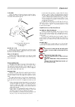
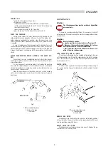
It's easy to connect (see picture below): just replace the washing
lance with the sandblasting one (1) and introduce the sand suction pipe
(2) into the container (3), using dry, quality sand suitable for this use
(quartz sand or siliceous sand).
When the water cleaner is started, the sand (a) is sucked, mixed to
water (b) and addressed to wards the surface to be treated , freeing it
from scales.
Fig.1
1. Water sandblasting lance
2. Sand suction pipe
3. Container
MAINTENANCE
Attention
The following operations must be carried out by qualified
personnel only.
To keep the machine perfectly efficient it's necessary to check it
out periodically. Please disconnect the electrical supply before starting
any operation.
Attention
Before starting to operate:
• stop the machine as instructed before ("Turning off")
• Disconnect the electrical supply turning off the dicon-
necting switch on the electrical switch board
• Close the water mains cock and unscrew the hose cou-
pling of the water entrance pipe.
HIGH PRESSURE PUMP, A.P. PUMP
The oil level in the pump must be checked out periodically by mean
sof the proper dip stick. Oil must be replaced after the first 50 working
hours, after wards every 500 working hours using Antifoam SAE 20/30
oil (oil capacity: 0,4 l).
WATER FILTER
The filter, which is placed into the plastic fitting at the beginning of
A.P. pump, must be frequently cleaned and carefully replaced to avoid
air suction.
Fig.2
1. Pressure adjustment valve
2. Detergent tap
3. Water filter
BURNER AND FILTER
Periodically clean the gasoil nozzle and check setting and condition
of the electrodes : the gasoil nozzle must be replaced every 200 hours
and the electrodes every 500 hours.
GASOIL FILTER AND PUMP
Periodically remove the gasoil pump and clean it. Replace the ga-
soil filter every 100 working hours.
9
1
3
2
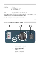
ENGLISH