background image

Note: Subject to errors and technical modifications!  
Windows® is a registered trademark of the Microsoft Corp.   
Status as at: 25.04.2022 – Revision 2-0

Bicker Elektronik GmbH
Ludwig-Auer-Straße 23
86609 Donauwörth · Germany
Tel. 

+49 (0) 906 70595-0

Fax 

+49 (0) 906 70595-55

E-Mail [email protected]

www.bicker.de

Summary of Contents for UPSI-1208DPx

Page 1: ...User Manual UPSI 1208DPx Bicker Elektronik GmbH Ludwig Auer Stra e 23 86609 Donauw rth Germany English UPS SYSTEM DIN RAIL...

Page 2: ...ns more detailed specified Indoor Outdoor Page 2 Warning Read User Manual at explanation Legend of used symbols supplemented 25 11 2020 Revision 1 4 Model UPSI 1208DP3 integrated 20 10 2021 Revision 1...

Page 3: ...88 kJ useful 1 59 Wh 1 08 Wh useful Ambient temperature Operating Storage Transport 20 65 C 30 65 C Operating altitude 4000 m Max permitted humidity 95 at 25 C no dew Dimensions W H D 63 x 120 x 100 m...

Page 4: ...6 8 10 12 14 16 18 20 22 24 26 28 30 0 1 2 3 4 5 6 7 8 9 10 Backupzeit min UPSI 1208DP2 0 10W Backup me min POUT W 0 20 40 60 80 100 120 140 160 180 200 220 240 260 280 300 0 10 20 30 40 50 60 70 80...

Page 5: ...Operating Storage Transport 20 50 C 30 55 C recommended state of charge 80 Temperature derating See derating curve on page after next Operating altitude 4000 m Max permitted humidity 95 at 25 C no dew...

Page 6: ...0 1 2 3 4 5 6 7 8 9 10 11 12 13 14 15 0 0 0 1 0 2 0 3 0 4 0 5 0 6 0 7 0 8 0 9 1 0 Iout A Backup time h 0 10 20 30 40 50 60 70 80 90 100 110 120 130 140 150 0 0 0 5 1 0 1 5 2 0 2 5 3 0 3 5 4 0 4 5 5 0...

Page 7: ...3 20 0 C At sub zero temperatures the charging time increases according to the physical properties of the cells increased internal resistance 0 1 2 3 4 5 20 10 0 10 20 30 40 50 60 70 Ambient temperatu...

Page 8: ...vection and installation position 21 F3 Description of connectors 23 F4 Dimensioning the upstream power supply 25 F5 Connecting diagram 26 F6 Initial operation 27 F7 Overview connector Counterpart wit...

Page 9: ...mode automatically The input voltage is passed through to the output and the integrated energy storage device is charged simultaneously The charging current depends dynamically on the load current at...

Page 10: ...UPS Gen Configuration Software is required for setting parameters and programming new firmware for all UPSI Gen devices under Microsoft Windows The software tool also shows the operating status of the...

Page 11: ...t put obviously damaged devices into operation e g dents burn marks rough contamination 9 Keep ventilation openings clear 10 Device must not be dropped 11 All parts of the device and accessories must...

Page 12: ...nding on load Current consumption IN UN IOUT IN ICHARGE 0 IMAX UN IOUT IN ICHARGE max IDYN UN IOUT IDYN BOOST ICHARGE 0 INO LOAD UN IOUT 0 ICHARGE 0 ICHARGE UN IOUT 0 ICHARGE max UPSI 1208DP2 8 1 A 9...

Page 13: ...for max 100 ms 10 8A for max 5ms Short circuit proof Yes No load proof Yes OUTPUT DATA BATTERY MODE Unless otherwise stated all specifications apply to 25 C ambient temperature 12 V DC input voltage a...

Page 14: ...J 3 88 kJ useful 1 59 Wh 1 08 Wh useful Charging time ICHARGE max App 5 min 20 sec Buffer time at IOUT 8 A App 33 sec ENERGY STORAGE UPSI 1208DP3 Charging method CC CV CP Nominal voltage UN 9 9 V End...

Page 15: ...gnal assignment NO Normally Open NC Normally Closed configurable via Software see UPS Gen2 software manual Connection method Lockable plug connector Conductor cross section solid 0 205 mm 1 3 mm 24 16...

Page 16: ...N Rail mounting EN 60715 Housing version Aluminium Dimension W H D 63 mm 120 mm 100 mm without front connectors and DIN Rail mounting bracket DATA INTERFACE RS232 Interface designation RS232 Numbers o...

Page 17: ...erature storage transport DP2 30 65 C DP3 30 55 C Max permitted humidity 95 at 25 C no dew Operating altitude 4000 m Climate class 3k3 EN 60721 Degree of pollution 2 Overvoltage category EN 61010 1 EN...

Page 18: ...ment 4 kV 8 kV Criterion B Electromagnetic HF field EN 61000 4 3 Frequency range Test field strength Frequency range Test field strength Comment 80 MHz 1 GHz 10 V m 1 4 GHz 2 GHz 3 V m Criterion A Fas...

Page 19: ...aviour that is corrected by the device itself EMISSION ACCORDING TO EN 55016 2 3 DOMESTIC Basic standard CE Fulfilled requirements according to EN 55016 2 3 CE Domestic Conducted emission from the pow...

Page 20: ...er of the manufacturer Bicker Elektronik GmbH Ludwig Auer Stra e 23 86609 Donauw rth Germany E Mail support bicker de Tel 49 0 906 70595 0 2 mm 120 mm 63 mm 8 5 9 mm 100 mm 44 mm 16 6 mm 9 7 10 mm Unl...

Page 21: ...orrect polarity Before commissioning check all the connections for correctness F2 Convection and installation position For these DIN rail versions vertical mounting on a horizontal rail DIN rails acco...

Page 22: ...UPSI 1208DPx Revision 2 0 22 DIN Rail mounting and DIN Rail profile according to EN 60715 2 3 4 1 Press down...

Page 23: ...e via software When closing the relay the resistor value between both contacts is approx 0 otherwise they are open load PIN FUNCTION 1 Relay contact 1 2 Relay contact 2 2 1 INPUT OUTPUT IN OUT Vin Vou...

Page 24: ...screw attachment M4 thread screw M3x6mm max at the front right corner on top of the device to connect functional earth if required The requirements for interference emission EN55016 2 3 see D1 General...

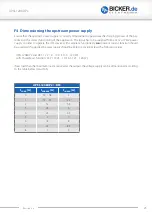
Page 25: ...vice with complete functionality no constant current function should be used and the upstream power supply should be able to provide at least the following values UPSI 1208DP2 and DP3 12 V 9 10 A 110...

Page 26: ...agram VIN VOUT ATTENTION 1 Note polarity 2 AWG16 wire should be used 1 5 mm2 CONNECTING ORDER 1 APPLICATION VOUT 2 DC SOURCE VIN 3 RELAY USB RS232 Dismantling order reverse to connection USB RS232 for...

Page 27: ...esholds at the input UPS function It must be ensured that the source supplies enough current to guarantee the charging process see chapter F4 Dimensioning the upstream power supply Even after disconne...

Page 28: ...act of a short circuit to the device depends on length and diameter impedance of the output wiring In case of a short circuit directly at the plugs a damage of the device can occur F10 Backup time in...

Page 29: ...recorded and the output will not be released again until the value falls below the maximum value UPSI 1208DP2 UPSI 1208DP3 Nominal output power IOUT Nominal x UOUT 96 W Threshold for detecting an ove...

Page 30: ...sec 84 sec 2 sec 5844 Ws 5 84 kJ UPS output is disconnected after 58 seconds because the output energy exceeds 5 57 kJ Example 3 E 72 W 2 sec 120 W 6 sec 96 W 2 sec 108 W 6 sec 84 W 3 sec 120 W 5 sec...

Page 31: ...s off briefly pause 2s Status Reboot Output is deactivated and time until reboot runs Reboot phase UPS FAILURES Quick flashing without pause Status UPS failure Output current too low UPS is deactivate...

Page 32: ...ail True Shutdown SOC Threshold Reached Max Backup Time Timeout Shutdown Timer Timeout Shutdown SOC Enabled Max Backup Enabled Shutdown Timer OS Enabled Ignition Timer Timeout Ignition Pin High True F...

Page 33: ...acity than actually required should always be used The less deep the packs are discharged the longer the service life lasts F16 Maintenance The UPS contains no serviceable parts In case of a malfuncti...

Page 34: ...a not intended Power Fail could be caused With maximum load the voltage at the input of the device must not undercut 11 5V Even after the upstream supply has been disconnected the device continues to...

Page 35: ...ions Windows is a registered trademark of the Microsoft Corp Status as at 25 04 2022 Revision 2 0 Bicker Elektronik GmbH Ludwig Auer Stra e 23 86609 Donauw rth Germany Tel 49 0 906 70595 0 Fax 49 0 90...

Reviews: