


User’s Manual UPSI-B-2405
Bicker Elektronik GmbH
||
Tel. +49 (0)906 70595-0
||
www.bicker.de
||
info@bicker.de
20
3 Display
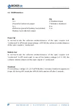
A 3-colour-LED can be connected to the LED connector 3 (UPSI-B-2405 case).
Pinning:
LED-connector 3
4 3 2 1
PIN
PIN
1 GND (reference)
3 Batterie Low (red)
2 Power LED (green)
4 n.c.
LED green:
The LED lights green, as long as input voltage is available (>20 V DC).
LED orange:
The LED lights orange, as soon as the DC UPS module UPSI-B-2405 switches into
the UPS mode (Input voltage <20 V DC).
LED red/orange flashing:
In UPS mode the LED flashes red/orange if the capacity of the connected
batterypack is low (Output voltage drops to <21 V).
LED red/green flashing:
The LED flashes red/green if
the connected batterypack is empty or defective.
the connection to the battery or fuse is defective.
The 3-colours-LED is included in delivery.


