background image

31

English

User’s Manual IUPS-401-Series

7.2  Model IUPS-401-110-B7

  T e c h n i c a l   d a t a

 Output power 

400 VA / 240 W

 Input voltage 

110 V AC ±15 %

 Input frequency 

50 / 60 Hz ±5 %

 Output voltage 

110 V AC ±15 %

 Output frequency 

50 / 60 Hz ±1 % 

 Charging time 

App. 8 h (90 % load)

 UPS Classification / Wave form 

VFD / Rectangular

 Protection 

Overload protection: UPS mode: 100…120 %, Alarm


120…190 %, Switch off 


Mains mode: Fuse


Overtemperature protection: Switch off

 Transfer time 

<6 ms

 Back up time 

100 W / 166 VA load  app. 5 min 


180 W / 300 VA load  app. 2…3 min  


 Interface 

See overview on page 33

 Temperature 

Operating: 0…+40 °C / Storage: 0…+40 °C

 Humidity  

Operating: 10…85 %, non-condensing


Storage: 10…90 %, non-condensing

 Dimensions 

146 x 253 x 42 mm ±0.5 mm 

 Weight (net) 

2.75 kg

  Product-specific data

 Transfer limit in mains / UPS mode 

92 V AC ±5 %

 Transfer limit into UPS mode  

126 V AC ±5 %

 in case of overvoltage at the input
 Type of battery 

2 x 6 V / 3 Ah maintenance-free lead-gel batteries (VRLA)

 Noise development 

<35 dbA

 Load sensor 

Switch off see overview on page 33 

 UPS Management Software 

See overview on page 33

 Reboot function  

See overview on page 33

 Button 

To switch off alarm sound press for app 1 sec.


To switch off UPS press for app 4 sec.


To switch on UPS (cold start, without mains supply) 


press for app 2 sec.

The service life of the batteries is app. 4…5 years at +20 °C and will decrease by half with each temperature increase of 10 °C according to EUROBAT. 
During storage the UPS has to be charged at least every 6 months.

Summary of Contents for IUPS-401

Page 1: ...Benutzerhandbuch User s Manual IUPS 401 Deutsch English IUPS 401 400VA...

Page 2: ...Benutzerhandbuch IUPS 401 Serie 2 Deutsch IUPS 401 mit Standard Frontblende IUPS 401 mit gewechselter schwarzer Frontblende IUPS 401 Serie Integrierte USV...

Page 3: ...tz 5 1 5 bertemperaturschutz 5 1 6 Austausch der Frontplatte 5 2 Sicherheit 6 3 Einbauanweisung 7 3 1 IUPS 401 B5 BB BC 7 3 2 IUPS 401 B1 B4 BA B9 110 B7 10 4 Bediendisplay 11 5 Schnittstelle und Soft...

Page 4: ...Die IUPS Internal Uninterruptible Power Supply ist eine integrierte USV 400VA 240W gedacht zum Einbau in den 51 4 Laufwerksschacht eines Computers Bei Netzbetrieb werden durch die internen Filter st r...

Page 5: ...h ren der bei Beseitigung der berlast erlischt 1 5 bertemperaturschutz Die interne Temperatur berwachung signalisiert eine auftretende bertemperatur durch die rote LED und eine akustische Warnung 1 6...

Page 6: ...nnungsfreiheit im System festzustellen 3 Bei der Montage ist auf sichere Befestigung der IUPS zu achten Zur Montage m ssen ausschlie lich die beigef gten Schrauben verwendet werden Keinesfalls d rfen...

Page 7: ...hst niedriger Temp eratur erlangen Sie eine Optimierung der Batterielebensdauer Vor Beginn der Arbeit Netzstecker ziehen 1 DSUB9 Verbindungskabel an der R ckseite der IUPS 401 anstecken und dort versc...

Page 8: ...dung 1 Das Verbindungskabel der IUPS 401 auf die 5 polige Stiftleiste und das Netzkabel der IUPS 401 am Slotblech aufstecken 2 Das USB Kabel vom Slotblech zum externen USB Port stecken Die Netzverkabe...

Page 9: ...as Mainboard stecken 2 USB Verkabelung Bitte berpr fen Sie die PIN Belegung des internen USB Kabels mit der PIN Belegung auf Ihrem Mainboard ACHTUNG Die PIN Belegungen m ssen bereinstimmen Eine Verpol...

Page 10: ...tur erlangen Sie eine Optimierung der Batterielebensdauer Vor Beginn der Arbeit Netzstecker ziehen 1 Netzstecker abziehen 2 Slotblech mit 5 pol Steuerkabeleinbauen 3 5 pol Steuerkabel an der IUPS eins...

Page 11: ...rt nt alle 3 Sekunden Batterie leer LED Die rote LED blinkt schnell wenn die Batterie schwach ist St rungs LED Tritt auf bei berlast bertemperatur und internem Fehler berlast Die rote LED leuchtet bei...

Page 12: ...r seriellen Schnittstelle des Computers verbunden werden Durch die Installation der Software RUPS2000 OEM 1 kann bei Netzausfall eine Warnmeldung am Monitor angezeigt werden 2 k nnen offene Dateien au...

Page 13: ...euchtet M glicher Grund 1 Netzspannung fehlt 2 USV ist ausgeschaltet 3 Sicherung defekt 4 USV keine Funktion Behebungsvorschlag 1 Netzspannung berpr fen 2 USV am Taster Frontplatte einschalten 3 Servi...

Page 14: ...0 40 C Lagerung 0 40 C Luftfeuchtigkeit Betrieb 10 85 RH nicht kondensierend Lagerung 10 90 RH nicht kondensierend Abmessungen 146 x 253 x 42 mm 0 5 mm Gewicht 2 75 kg Produktspezifische Daten Umscha...

Page 15: ...keit Betrieb 10 85 RH nicht kondensierend Lagerung 10 90 RH nicht kondensierend Abmessungen 146 x 253 x 42 mm 0 5 mm Gewicht 2 75 kg Produktspezifische Daten Umschaltschwelle Netz USV Betrieb 92 VAC 5...

Page 16: ...d eines Netzausfalls und der schon eingeleiteten Shutdown Phase von Windows die Netz spannung wieder zur ck so schaltet die USV nach Ablauf der Shutdown Zeit den PC aus und nach ca 5 Sek in Verbindung...

Page 17: ...g des Mainboards beachten RUPS 2000 OEM USV Management Software im Lieferumfang enthalten Statusanzeige und Alarm Statusanzeige Alarm Alarmton LED abschaltbar USV Normalbetrieb gr n Batterieladung Net...

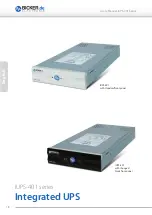
Page 18: ...18 English User s Manual IUPS 401 Series IUPS 401 with standard front panel IUPS 401 with changed black front panel IUPS 401 series Integrated UPS...

Page 19: ...ion 21 1 5 Overtemperature Protection 21 1 6 Replacement of front panel 21 2 Safety 22 3 Installation Instruction 23 3 1 IUPS 401 B5 BB BC 23 3 2 IUPS 401 B1 B4 BA B9 110 B7 26 4 Display 27 5 Interfac...

Page 20: ...ible Power Supply IUPS is an integrated UPS unit 400 VA 240 W and designed for mounting into a 5 1 4 drive slot of a computer Interfering and dangerous overvoltage transients and voltage surges are ef...

Page 21: ...ent sound is gene rated which will stop when the overload is eliminated 1 5 Overtemperature Protection When an overtemperature is detected by the internal temperature control this is indica ted by the...

Page 22: ...onnect mains and make sure that the system is voltage free 3 During the installation make sure the IUPS is safely mounted Only use the included screws for mounting the unit Make absolutely sure that n...

Page 23: ...install the IUPS into the computer at a location with preferably low temperature Disconnect mains before starting the installation 1 Connect DSUB9 connection cable at the back of the IUPS and fasten s...

Page 24: ...ction cable of the IUPS 401 to the 5 pole pin and socket connector and the mains cable of the IUPS 401 to the slot bracket 2 Connect the USB cable from the slot bracket to the external USB port Connec...

Page 25: ...nd socket connector jto the mainboard 2 USB connection Please compare the pin assignment of the internal USB cable to the pin assign ment of your PC mainboard WARNING The pin assignments must comply A...

Page 26: ...th preferably low temperature Disconnect mains before starting the installation 1 Disconnect mains 2 Install slot bracket with 5 pole control cable 3 Connect 5 pole control cable at the IUPS 4 Connect...

Page 27: ...ED The red LED flashes quickly when the battery is low Failure LED This failure indication is engaged in case of overload overtemperature or an internal failure Overload In case of an overload the red...

Page 28: ...into the delivery of the software package When the software RUPS2000 OEM is installed 1 a warning message can be displayed at the monitor in case of mains power failure 2 open files can be stored auto...

Page 29: ...s on Possible cause 1 No mains voltage 2 UPS is switched off 3 Fuse is defect 4 No UPS function Possible countermeasure 1 Check mains voltage 2 Switch on UPS at the front panel button 3 Call service s...

Page 30: ...midity Operating 10 85 non condensing Storage 10 90 non condensing Dimensions 146 x 253 x 42 mm 0 5 mm Weight net 2 75 kg Product specific data Transfer limit in mains UPS mode 190 VAC 5 Transfer limi...

Page 31: ...Storage 10 90 non condensing Dimensions 146 x 253 x 42 mm 0 5 mm Weight net 2 75 kg Product specific data Transfer limit in mains UPS mode 92 VAC 5 Transfer limit into UPS mode 126 VAC 5 in case of o...

Page 32: ...in after app 30 sec 5 minutes depending on the battery capacity the higher the capacity the shorter the restart time This latency is required to ensure suffi cient energy for a secure shutdown in case...

Page 33: ...s red flashing quickly 2 sec stillness Battery defect red flashing quickly Model overview IUPS 401 110 B7 Article Interface Load sensor UPS management software No switch off IUPS 401 110 B7 SERIAL D S...

Page 34: ...ma Microsoft Corp Subject to errors and technical modifications Windows is a registered trademark of Microsoft Corporation Stand Issued 10 11 2017 Bicker Elektronik GmbH Ludwig Auer Stra e 23 86609 Do...

Reviews: