


38
18
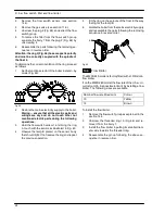
Ignition and detection electrodes
18.1
Function
Three electrodes are fitted on the burner. Two of them
are the ignition electrodes and are fitted near the front
part of the burner. The ignition sparks take place be-
tween their metallic edges over the central ramp of the
burner during the ignition sequence.
The third electrode is the detection electrode and it de-
tects the presence of the flame.
Ignition
Detection
Male
Female
Fig. 74
18.2
Checks
n
Check the position of the electrode edges
Warning: isolate the boiler from the mains
electricity supply before removing any
covering or component.
1
Remove all the case panels, the sealed chamber
lid and the combustion chamber lid.
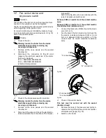
2
Check for the correct distance between the me-
tallic edges of the ignition electrodes (see
Fig. 75).
Ignition
4 mm
Fig. 75
3
Check the integrity of the detection electrode and
ensure that its metallic edge is correctly placed
over the ramp of the burner.
n
Check the connection wires.
Warning: isolate the boiler from the mains
electricity supply before removing any
covering or component.
1
Remove all the case panels, the sealed chamber
lid and the combustion chamber lid.
2
Check for the integrity of the insulation of wires
which connect the electrodes to the ignition de-
vice.
18.3
Removal
Warning: isolate the boiler from the mains
electricity supply before removing any
covering or component.
1
Remove all the case panels, the sealed chamber
lid and the combustion chamber lid.
2
Disconnect the electrode wires from the full se-
quence ignition device.
3
Remove the burner by unscrewing the four
screws placed at the right and left sides of the
burner.
3b
For models M90D.28S and M90D.28SR, remove
also the plate C (see Fig. 78 on page 39).
4
Unscrew the screws
A
(Fig. 76) which hold the
electrodes to the burner.
A
Fig. 76
5
Extract the electrodes from the burner.
6
Assemble the electrodes carrying out the removal
operation in reverse order.
Refer to Fig. 74 in order to recognise the elec-
trodes and to correctly connect the wiring.
Note: the metallic edge of the detection electrode is
longer than the one of the ignition electrodes.
Warning: After cleaning or replacement as
detailed above refer to section
Combustion
analysis check
in the chapter
Maintenance
of
the installation instructions manual.
Summary of Contents for RIVA PLUS M90S.24S
Page 2: ......


