


Technical information
15
4.3
Hydraulic specifications
0.0
0.1
0.2
0.3
0.4
0.5
0.6
0
200
400
600
800
1000 1200 1400
0
10
20
30
40
kPa bar
l/h
60
50
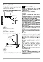
Fig. 4.3
The hydraulic specifications in Fig. 4.3 represent
the pressure (available head for the central heat-
ing system) as a function of the flow rate.
The load loss due to the boiler has already been
subtracted.
Output with thermostat cocks shut off
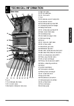
The boiler is fitted with an automatic by---pass
valve (45 on page 13), which protects the primary
heat exchanger.
In case of excessive reduction or total blockage of
water circulation in the central heating system
owing to closure of the thermostatic valves or sys-
tem component cocks, the by---pass valve ensur-
es a minimum flow of water through the primary
heat exchanger.
4.4
Expansion vessel
Note: this boiler is designed for operation only
in a sealed central heating system
The height difference between the pressure relief
valve and the highest point in the system may be
10m at most.
For greater differences, increase the pre---load
pressure in the expansion vessel (44 on page 13)
and the system, when cold, by 0.1 bar for each
additional 1m.
For 24 Kw and 28 Kw
Capacity
l
6,0
Pre---load pressure
kPa
bar
100
1,0
Maximum volume of water
in the system *
l
94
For 32 Kw
Capacity
l
7,0
Pre---load pressure
kPa
bar
100
1,0
Maximum volume of water
in the system *
l
109
Tab. 4.1
* Where conditions are:
---
Average maximum temperature of the system
is 85
°
C
---
Initial temperature when filling up the system is
10
°
C
For systems (24 Kw and 28 Kw) with volumes
greater than 94 l, an additional expansion vessel
must be provided.
For systems (32 Kw) with volumes greater than
109 l, an additional expansion vessel must be pro-
vided.
IN
S
TA
LLA
TI
O
N