4
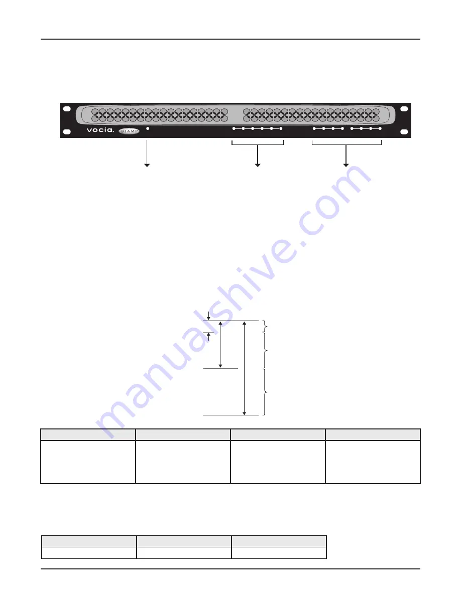
VI-6 frOnt Panel
Setup and Use
The Vocia software provides an intuitive interface for configuration, DSP equalization, and programming of the VI-6. The information supplied
by this manual relates to physical connections and assignment. For more details on software setup, please consult the Vocia Help File.
1 . Power Indicator LED
On the left of the front panel, the VI-6 has a single LED that indicates power and connectivity status:
1. Not illuminated: The device is not powered.
2. Flashing green: The unit is receiving power but not data, or the unit has not been configured correctly.
3. Solid green: The unit is operational, has been configured and is receiving PoE.
2 . Signal LEDs
Six LEDs located in the center of the front panel act as audio signal identifiers for the four input channels and are useful for setting optimum signal
levels. Each LED has four states. please see the table below for the signal mapping to each of the LEDs. Detailed metering of current output levels
can be obtained in real time via the Vocia software interface.
3 . Control LEDs
The control LEDs signal the current state of the control I/Os. The first four are input status indicators, and the second four are output status indicators.
They have three states:
1. power Indicator LED
2. Signal LEDs
3. Control LEDs
Clip
-3
-18
-48
Red
Yellow
Green
Nominal
Threshold
Red
Yellow
Green
Dark
Signal above clip threshold
> -3dBFS
Signal above nominal but below
clip threshold
> -18dBFS
< -3dBFS
Signal above minimum but
below nominal threshold
> -48dBFS
< -18dBFS
Signal below minimum threshold
< -48dBFS
Yellow
Green
Dark
Relays are energized
> input threshold
Not active
Audio Channel
Control Inputs
Control Outputs
Power/
Network
1 2 3 4 5 6
1 2 3 4 1 2 3 4
Input 6
Summary of Contents for VOCIA VI-6
Page 11: ...11 compliance ...
Page 12: ...12 compliance ...


