Qt X Sound Masking System
Installation and Operation Guide
page 13
EMITTER INSTALLATION
(Qt X 300/600 models)
Each cable run has a maximum length of 1000 ft (305m).
The tables that follow give the number of emitters that may be installed in a given
cable run, output, etc. per Qt X device. Each output has two identical runs (A and
B). The emitters in both output runs are controlled equally and
must
be of the
same emitter type.
Qt X 300 - Emitter Installation Totals
Emitter Type
Per Cable Run
Per Output
Total (3 Outputs)*
Standard
60
120
360
Active
50
100
300
Qt X 600 - Emitter Installation Totals
Emitter Type
Per Cable Run
Per Output
Total (6 Outputs)*
Standard
60
120
720
Active
50
100
600
* Output total assumes the same emitter type in each output. Total emitter counts
will vary per device if both standard and active emitters are present in a system.
NOTE:
for open ceilings or other installations that do not secure to a tile, other mounting
options are available (such as hanging pendants). See Biamp's product offerings for
information.
NOTE:
Active and passive emitters are installed identically. On the passive emitters, the
input and output ports are labeled as such: INPUT, OUTPUT.
On the active emitters, the input is labeled
and the output as
. The input
can be located by identifying the jack nearest the seismic keyhole on the rear
of the emitter
It is critically important that the emitters are wired / located following the layout
and wiring diagram from the Design Team to prevent any signal interference. In
addition, please review the general emitter placement and wiring information on
pages 14-18
.
NOTE:
For Active Emitters, a Qt Power Injector (purchased separately) will need to be
installed directly adjacent to the first emitter. Each output on the power injector can power
up to 25 Active Emitters (up to 50 for each cable run). A Qt Power Supply (also purchased
separately) is necessary to power the injectors and can power up to six (6) Qt power
Figures 16-17
).
1. Determine emitter installation locations based on
the system plan provided by the Design Team.
R
un cables from the controller to the first emitter
location for each run per output (Figure 15). Label
the cabling such that the location of the run is easily
identifiable at the point of connection
to the Qt X. For example: Output 1A
- main office, Output 2A - Lobby, etc.
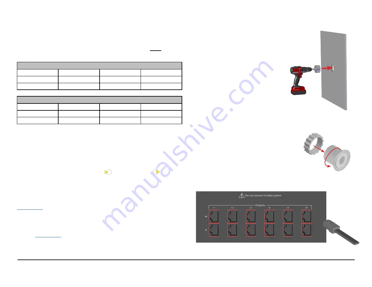
2. Ceiling tile mounting - use an
appropriate tool and drill a 2.5"
(64mm) size hole in the center of
the appropriate ceiling tiles. Cut from
the front of the tile. A hole saw bit is
included with Qt X 300/600 models.
Other mounting options are available
for open and structural ceilings. They include: Beam Brackets, Pendant
Mounts, Drywall Mounts, New Construction Brackets, Plenum Back cans,
and Universal Brackets.
3. Power on the Qt X controller and set the standard
sound masking level to 0 dB for the desired output
# and associated zone.
4.
Install the first emitter in the ceiling tile by
pushing the emitter through the front of the hole in
tile and securing it with the locking ring. Connect
the cable run from the Qt X output RJ45 connector
to the INPUT connector of the first emitter (Figure 16).
The input jack has the
rounded tab above it and can help if you can't see it easily.
Tile Front
Figure 12.
Emitter runs from the Qt X 300/600 controllers
(Qt X 600 panel shown)


