


6.1
6. Foundation Requirements
The Foundation System for your new System S varies
depending on the specifics of your site, and the
requirements of the governing municipality. You may choose
to install your module as a temporary structure, similar to a
shed, which may have reduced permitting requirements, but
will be less stable and secure for long term use, or you may
choose to install as a permanent structure. For a permanent
structure, your municipality or governing body may require
further documentation and permitting prior to install. Please
note, that the required connection to the foundation may
vary based on local or regional codes or ordinances and can
vary depending on the specifics of your site. Therefore, BHC
does not provide any hardware to connect the sauna to its
foundation and suggests confirming the requirements with
your AHJ.
6.1 Temporary Structure
For a temporary structure, we suggest four 24” x 24” x 6”
concrete pavers to be provided by you, to be positioned to
support the corners of your module. Please note that these
requirements may vary based on local or regional codes or
ordinances, and all work must conform to the requirements
outlined by the governing body.
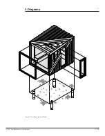
6.2 Permanent Structure
For a permanent installation, we recommend four 8”
sonotube formed footings and piers to be arranged in
an 8’x8’ square at the desired location of your module.
The piers should provide a platform that is both level and
straight, and should align with the framing members of
your System S. The floor system has blocking running
perpendicular to the floor framing to allow you to attach the
site-specific required Hold-Down/Brackets. Please note
that these requirements may vary based on local or regional
codes or ordinances, and all work must conform to the
requirements outlined by the governing body.
Figure 6.1 Temporary Foundation Diagram
Figure 6.2 Permanent Foundation Diagram
Figure 6.2 Bearing Location Section
System S
Module
2'-0"
typ.
2
'-
0
"
ty
p
.
8
'-
0
"
8
1
2
"
1
'-
3
1
2
"
5
'-
5
"
1
'-
3
1
2
"
8
1
2
"
1'-0"
2'-0"
5'-8
1
2
"
1'-3
1
2
"
8
1
2
"
24" x 24" x 8"
concrete
pavers (typ.)
door
g
la
z
in
g
10'-0"
System S
Module
10'-0"
8
'-
0
"
8
1
2
"
6
'-
7
"
8
1
2
"
2'-3
1
2
"
7'-0"
8
1
2
"
door
g
la
z
in
g
8" concrete
sonotube footings
(typ.)
9
'-
7
3 8
"
blocking running
perpendicular to
floor framing
8" point load
bearing area
8" point load
bearing area
© 2021 The Backcountry Hut Company
211108