background image


17 

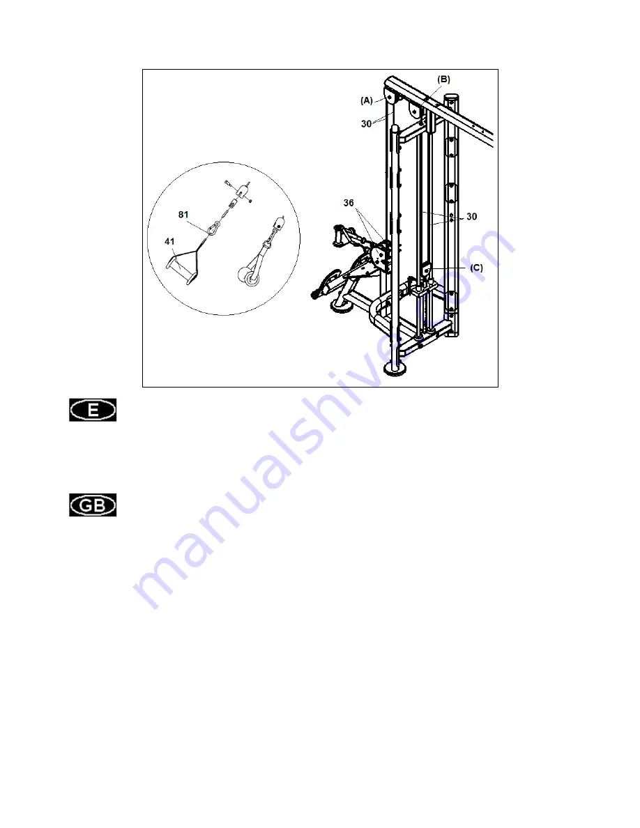
Fig.8 


Coja el cable (30) y enebre el cable en las poleas (A) y (B) que se encuentra en el soporte poleas (3) y 

en la polea (C) hasta los soportes poleas (36) tal y como se muestra en la figura 8. 

Coja los enganche de cadenas (81) y una los extremos del cable (30) con los tensores y únalos al asa 

(41) como muestra la figura 8. 


Take the cable and thread the cable on pulleys (A) and (B) located in the pulley bracket (3) and through 

the pulley (C) to the double pulley bracket (36) as shown in fig 8. 

Take the chain hook (81) and join the end of cable (30), which you have just threaded through, with the 

cable tensioner and join to the handle (41). Fig.8. 


Summary of Contents for L360FS

Page 1: ...L360FS Instrucciones de montaje y utilización Instructions for assembly and use ...

Page 2: ...150kg Las reparaciones incorrectas y o las modificaciones estructurales del equipo Ejemplo Retirar o el reemplazar piezas no originales pueden poner en peligro la seguridad del usuario Los componentes dañados pueden poner en peligro su seguridad y o reducir curso de la vida del equipo Por esta razón las piezas dañadas se deben sustituir inmediatamente y el equipo mantenerlo fuera de uso hasta que ...

Page 3: ...kg Incorrect repairs and or structural modifications to the equipment E g Removal of parts or non original replacement parts can endanger the user s safety Damaged components may endanger your safety and or reduce the useful life of the equipment For this reason damaged parts must be replaced immediately and the equipment taken out of use until it is repaired Use only original BH spare parts If th...

Page 4: ...egurarse de que no falta ninguna pieza para el montaje del equipo en la primera fase Take the unit out of its box check and identify the parts against the list in Fig A and Fig B to ensure that there are no missing parts for the initial assembly stage of the equipment Fig A Nº Nº 1 2 2R 1 2L 1 3 1 4 1 5 1 6 1 7 1 ...

Page 5: ...8 1 9 2 10 2 11 2 13 1 14 1 15 1 16 1 ...

Page 6: ...17 1 20 4 21 2 28 1 29 2 30 1 ...

Page 7: ...31 1 32 1 34 8 36 2 38 5 39 4 40 6 41 7 ...

Page 8: ...42 8 43 4 44 8 48 1 81 7 ...

Page 9: ...18 M 12 1 126 Hex Key S 3 16 1 127 Hex Key S 4 1 128 Hex Key S 6 1 129 Hex Key S 8 1 NOTA La descripción de las piezas con respecto a las figuras corresponden siempre a la posición de la persona en el equipo para la realización del ejercicio NOTE The description of the parts with respect to the figures always corresponds to the position the person adopts on the equipment when exercising ...

Page 10: ...rníllelos con los tornillos 90 junto con las arandelas 107 y tuercas 117 tal como se muestra en la figura 1 al soporte inferior 5 y al soporte superior 4 INSTRUCTIONS FOR ASSEMBLY Rest on the floor the main support 5 Place in lateral bars 1 2R 2L the adjusting pads 40 and tighten the screws with washers and nuts provided inside the pads 40 Place the lateral bars 1 2R 2L the plates 38 the upper pul...

Page 11: ...orníllelos con los tornillos 89 junto con las arandelas 107 y tuercas 117 manteniendo la posición tal como se muestra en la figura 1 Tighten the arm support 3 to the upper support 5 with screws 89 washers 107 and nuts 117 maintaining the position as shown in Fig 1 ...

Page 12: ...que la anilla del selector 43 en el casquillo central de la pesa guía 39 Realice el mismo montaje para los otros tres lados Place the weight stop 42 on the weight stack insert the weight guide bars 34 Then place the weights provided 130 131 132 the heavier weights always at the bottom Finally fit the guide weight with the selector bar 39 tighten the top of weight guide bars using washers 44 and sc...

Page 13: ... soporte 8 con los tornillos 90 junto con las arandelas 107 y las tuercas 117 y al soporte principal 5 con los tornillos 93 junto con las arandelas 107 y las tuercas 117 Place the adjusting pad 40 in the rower support 6 and screw with the screw washer and nut included in the pad 40 Place the bracket 8 on the bars 1 and tighten with the screws 90 along the washers 107 and nuts 117 Bring the rower s...

Page 14: ...e del banco remo tal y como indica la figura 5 y fíjelos con los tornillos 83 junto con las arandelas 106 y las tuercas 116 y apriete fuertemente Place the fixed plate 32 on the rower support 6 and with the screws 97 tighten securely Place the footrest bracket 7 on the rower support 6 and with the screws 84 and washers 107 tighten securely Place the double pulley brackets 36 in the rower support b...

Page 15: ...ipal 5 Atorníllelo en la parte superior junto con la pletina 16 al soporte 4 con los tornillos 93 junto con las arandelas 107 y las tuercas 117 y al bastidor principal 5 según la figura 6 Place the adjusting pad 40 in the support 13 and screw with the screw washer and nut included in the pad 40 Insert in the adjusting tube 14 the selector frame 15 as shown in Fig 6 Position the adjusting tube 14 i...

Page 16: ...gura 7 Atorníllelo con los tornillos 90 junto con las arandelas 107 y las tuercas 117 Realice el mismo montaje descrito anteriormente con el brazo derecho 11R Place the lower support arm Buttlerfly 10 in the side arms 2L and 1 as shown in Figure 7 Screw the screws 90 with washers 107 and nuts 117 A tight time place the Butterfly arm shaft 11 in the bracket 10 and enter the upper arm shaft Buttlerf...

Page 17: ...adenas 81 y una los extremos del cable 30 con los tensores y únalos al asa 41 como muestra la figura 8 Take the cable and thread the cable on pulleys A and B located in the pulley bracket 3 and through the pulley C to the double pulley bracket 36 as shown in fig 8 Take the chain hook 81 and join the end of cable 30 which you have just threaded through with the cable tensioner and join to the handl...

Page 18: ...de cadenas 81 y una el extremo del cable 28 con el tensor y únalo al asa 41 como muestra la figura 9 Attach the end of the cable 28 to the cable tensioning nut as shown in Figure 9 Take the other end of the cable 28 and looking the arrows shown thread it through the pulley marked as D E F G H I Then thread the end of the cable 28 through the pulley 28 Take the chain hook 81 and join the end of cab...

Page 19: ...igura 10 Realice el mismo montaje para el cable del brazo Butterfly 11R descrito anteriormente Attach the end of the cable 29 to the cable tensioning nut as shown in figure 10 Take the other end of the cable 29 and looking the arrows shown thread it through the pulley marked as K L M N and O Take the chain hook 81 and join the end of cable 29 which you have just threaded through with the cable ten...

Page 20: ... 17 and B as shown in fig 11 Take the chain hook 81 and join the end of cable 31 which you have just threaded through with the cable tensioner and join to the handle 41 Fig 11 MUY IMPORTANTE Una vez realizado el montaje compruebe que todos los tornillos que han sido montados en esta maquina están fuertemente apretados VERY IMPORTANT After assembling the unit check that all of the screws have been ...

Page 21: ...L360FS ...

Page 22: ...A GB958DS2 11 A L360FSK1100 43 A IE95191400 75 A IN D20020802 107 A GB9510DS2 12 A L360FSK1200 44 A IT93252800 76 A HF900 03A1002 108 A GB9512DS2 13 A L360FSK1300 45 A IZ70010600 77 A KFFT0700 109 A DQ10DS2B 14 A L360FSK1400 46 A IT90013800 78 A GB30151104 110 A DQ10DS2D 15 A L360FSK1500 47 A IT80101800 79 A GB27661804 2Z 111 A DQ16DS2 16 A L360FSK1600 48 A CMJ61752100 80 A GB2766005 2Z 112 A YDQ1...

Page 23: ...SK3000 60 A TBT12100 92 A GB5780M10 100DS20 124 A GB17880 5M8 16 5DCS17 29 A L360FSK3100 61 A IT9008B3800 93 A GB5780M10 105DS20 125 A LHφ6 8 1DS2 30 A L360FSK3200 62 A HVCORE5400 94 A GB5780M10 115DS20 130 A IT80033200ST 31 A L360FSK3300 63 A M02502000 95 A GB5780M10 120DS20 131 A IT80033300ST 32 A L360FSK3400 64 A HF985A1800 96 A CNLM8 20DS20 132 A IT80124400ST ...

Page 24: ...hina Co Ltd Block A NO 68 Branch Lane 455 Lane 822 Zhen Nan RD Li Zi Yuan Putuo Shanghai 200331 P R C Tel 86 021 5284 6694 Fax 86 021 5284 6814 e mail info i bh cn BH HIPOWER UK Tel 02037347554 e mail sales uk bhfitness com AFTER SALES UK Tel 02074425525 e mail service uk bhfitness com BH HIPOWER FRANCE SAV FRANCE Tel 33 0810 000 301 Fax 33 0810 000 290 savfrance bhfitness com BH Germany GmbH Alte...

Reviews: