Betts CH46949LHT Installation And Maintenance Manual Download Page 6


Form Title: 

Document #: 

INSTALLATION AND MAINTENANCE MANUAL 

MM-CH004 

(Form: DEF-006A-1) 

Revision: 

0


Document Title: 

Date: 

EXTERNAL CHEMICAL HYDRAULIC VALVE


Oct. 20, 2020 

Page:


6 of 10


Betts Industries Inc.   

   814·723·1250   

   1800 Pennsylvania Ave. West   

   Warren, PA 16365   


www.BettsInd.com


Print Date: 1/22/2021   

This form is considered uncontrolled 24 hrs. after print date.


Relieve hydraulic pressure and test valve.  See section 5.1. 

6.2  Rebuilding valve using replacement kit of PTFE parts 

  CH75296TF - Includes items 

– 3,5,7,8,9,10,16,17,19  

  CH75296TFTS - Includes items 

– 3,5a,7,8,9,10,16,17,19  


Disconnect hydraulic line.  


Hold valve in vice by cap collar (2).  


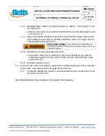
Unscrew indicator pins (21) and piston holder assembly (15 and 20).  


Unscrew piston (15) from piston holder (20) by 
holding piston holder (20) in vice and using allen 
wrench in end of piston (15).  

  Inspect piston (15) for scratches or pitting.  

Replace if these cannot be easily removed by 
polishing.  


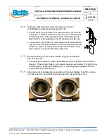
Using care not to damage the seal surface of the 
piston holder (20), remove the O-ring seal (3) and 
seal washer (19). 


Insert new seal washer (19) and O-ring (3) being 
very careful not to kink the O-ring (3). 


Apply lubricant to O-ring seal surface of piston (15) 
and also apply a high quality removable thread 
lock compound to threads of piston (15) and 
assemble to piston holder (20).  

  Torque piston to approximately 30 ft-lbs. 


Set piston assembly aside. 


PRE-LOADED SPRING:  

Use caution when unloading and 

loading spring; force is high and could cause bodily harm if not 
contained properly. 

PISTON

HOLDER

ASSEMBLY

INDICATOR PINS

PISTON

SEAL
WASHER

O-RING

PISTON

HOLDER

Summary of Contents for CH46949LHT

Page 1: ...sylvania Ave West Warren PA 16365 www BettsInd com Print Date 1 22 2021 This form is considered uncontrolled 24 hrs after print date PART NUMBERS Including but not inclusive CH46955SST CH46955LHT CH46...

Page 2: ...rform maintenance on this equipment 1 5 As with any maintenance work proper safety gear and procedures must be used at all times A list of hazards may include but are not limited to contents under pre...

Page 3: ...O Ring Seal 1 Tef Sil 75206TS 12 4x3 Body Assembly 1 316 Stainless 26099SS 4 Disc 1 316 Stainless 16743SS 4x3 Jacketed Body Assembly 316 Stainless 35086SS Hastelloy C 22 Trim 16743LH 4x4 Body Assembly...

Page 4: ...8 a 2 3 5 1 500 psi minimum hydraulic line pressure required to operate valve but do not exceed 3 000 psi hydraulic line pressure 3 6 A complete information page can be found in our catalog Section 35...

Page 5: ...mbly and Rebuild Instructions for proper repair procedures 6 0 Disassembly and Rebuild Instructions 6 1 To replace disc 4 and or seat 5 Attach hydraulic line and slightly open valve Hold cap collar 2...

Page 6: ...ly 15 and 20 Unscrew piston 15 from piston holder 20 by holding piston holder 20 in vice and using allen wrench in end of piston 15 Inspect piston 15 for scratches or pitting Replace if these cannot b...

Page 7: ...not to damage the lower stem 14 by applying too much pressure with the vice If lower stem 14 remains in valve body after the seal retainer ring 18 was removed continue to hold the cap collar 2 and ins...

Page 8: ...d or pitted the valve body 12 must be replaced Remove seat 5 using care to prevent damage or scratches to the seat area of the flange Inspect seat area of flange Valve body must be replaced if there i...

Page 9: ...em 6 and while holding the cap collar 2 carefully install lower stem 14 to upper stem 6 compressing the main spring 13 PRE LOADED SPRING Use caution when unloading and loading spring force is high and...

Page 10: ...Cause Solution Valve drifts closed Hydraulic pump malfunction See MM HP001 for hydraulic pump trouble shooting guide Air in system Loosen fittings on all valves Operate pump until all air is bled fro...

Reviews: