10
Ensamble de cajón
8.
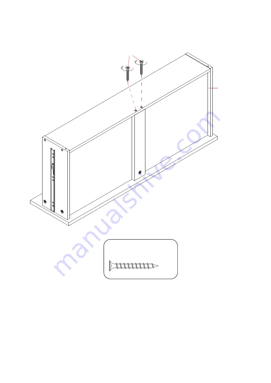
Fijar el respaldo del cajón (N) en el soporte inferior del cajón (Q) con dos tornillos de 38 mm (7) con un desarmador estrella.
7
P
N
O
Q
Tornillo M4 x 38 mm
(2 usados en este paso)
⑦
Page 1: ...parts are missing DO NOT return this item to the store where it was purchased Please call our customer service number and have your instructions and parts list ready to provide the model name part nam...
Page 2: ...0 lb 22 6 kg FITS UP TO MOST 80 FLAT PANEL TVs MAXIMUM LOAD 135 lb 61 2 kg THIS UNIT IS NOT INTENDED FOR USE WITH CRT TVS USE ONLY WITH FLAT PANEL TVS AND AUDIO VIDEO EQUIPMENT MEETING RECOMMENDED SIZ...
Page 3: ...ARY CAM LOCK SYSTEM OPERATION HOW THE KNOCK DOWN KD ASSEMBLY SYSTEM WORKS 1 Screw cam bolt into the pre drilled small holes on panel Connect both panels together making sure cam bolt goes into pre dri...
Page 4: ...C Base Front Stretcher Qty 1 D Base Back Stretcher Qty 1 E Base Side Stretcher Qty 2 F Left Side Panel Qty 1 G Partition Panel H Right Side Panel I Left Door Qty 1 Qty 1 Qty 1 J Right Door Qty 1 K Ad...
Page 5: ...rew Qty 22 1 extra Qty 18 1 extra Qty 48 2 extra 7 M4 x 38 mm Screw 8 M4 x 50 mm Screw 9 M3 x 15 mm Pan Head Screw Qty 12 1 extra Qty 12 1 extra Qty 4 1 extra 10 Magnetic Catch 11 Corner Connector 12...
Page 6: ...rt four M6 x 30 mm Wood Dowels 4 into the inner holes of the Drawer Back Panel N Tap it in with a rubber mallet if necessary Make sure that you use a small amount of glue with both ends of all dowels...
Page 7: ...7 Drawer Assembling 4 Slide the Drawer Bottom Panel R into the grooves between the Drawer Side Panels O and P until fully inserted into the Drawer Back Panel N P R O N...
Page 8: ...Drawer Assembling 5 Glue one M6 x 30 mm Wood Dowel 4 into the back center hole of the Drawer Bottom Support Q and attach it to the Drawer Back Panel N M6 x 30 mm Wood Dowel 1 used in this step P O N 4...
Page 9: ...Panels O and P and the Drawer Bottom Support Q with six M6 x 30 mm Wood Dowels 4 and five Small Cam Locks 1 Refer to page 3 on Cam Lock system operation supplement Make sure that Drawer Bottom Panel R...
Page 10: ...10 Drawer Assembling 8 Fasten the Drawer Back Panel N to the Drawer Bottom Support Q with two 38 mm Screws 7 using a Phillips screwdriver M4 x 38 mm Screw 2 used in this step 7 P N O Q...
Page 11: ...ttach one Drawer Handle 14 to the outside of Drawer Front M using two provided Handle Bolts 15 10 Repeat the same procedure to assemble the other drawer 15 M P O 14 Handle Bolt 2 used in this step Han...
Page 12: ...ur Corner Connectors 11 to the Base Side Stretchers E at the inner joints with the provided Washer Head Screws 6 Proceed to fasten the Corner Connetors 11 to Base Front and Back Stretchers C and D wit...
Page 13: ...13 Assembly Instructions 13 Tightly screw two Floor Levelers 16 into the threaded inserts on the Base Front Stretcher C and set to the correct height Floor Leveler 2 used in this step D C E E 16 16...
Page 14: ...tom Panel B 15 Align the large holes on the assembled base with with the inserted Wood Dowels 5 on the Bottom Panel B and press them together Secure them in place with twelve 50 mm Screws 8 M4 x 50 mm...
Page 15: ...15 Assembly Instructions 16 Securely screw the Cam Bolts 3 into the designated small holes on the Bottom Panel B using a Phillips screwdriver 3 B Cam Bolt 6 used in this step...
Page 16: ...ing a Phillips screwdriver 18 Align two Magnetic Catches 10 to the pilot holes on the Top Panel A as shown And then attach the Magnetic Catches 10 in place using two Pan Head Screws 9 per catch 10 9 3...
Page 17: ...rtical panels F G and H at both ends 20 Align and attach the Side Panels F and H and Partition Panel G between the Top and Bottom Panels A and B by engaging twelve Large Cam Lock 2 as shown B A F G H...
Page 18: ...22 Set the assembly on its front edges Unfold the Back Panels L and lay them to the back edges of the assembled unit Make sure that the overlaps on the panels are even all the way around Attach the B...
Page 19: ...o the holes at your desired height inside right compartment Tilt and rest the Adjustable Shelf K onto the Shelf Pins 12 25 Plug the Cam Lock Covers 13 onto the visible cam locks to conceal the cams Sh...
Page 20: ...Hinge Arm under the bolt head on the back of Hinge Base Make sure that both door hinges engage and function properly Tighten the bolt on the Hinge Base to lock the hinges in place 28 Repeat the same...
Page 21: ...lide Tracks and push the drawers carefully inside until it stops NOTE If the drawer does not go in smoothly please take it out and repeat the step If you need to remove the drawer please pull the draw...
Page 22: ...hardware included is for wooden stud wall construction It must be attached to a wall stud Depending upon your wall construction different anchor hardware maybe required Please contact your local hardw...
Page 23: ...trolled environment Extreme temperature and humidity changes can cause fading warping shrinking and splitting of wood It is advised to keep furniture away from direct sunlight as sun may damage the fi...
Page 24: ......
Page 25: ...est faltante no retorne est producto a la tienda donde lo compr Por favor llame a nuestro departamento de ayuda al cliente teniendo su instructivo y lista de partes para proveer el modelo nombre de p...
Page 26: ...GA 50 lb 22 6 kg PARA LA MAYORIA DE TV S DE 80 PANTALLA PLANA M XIMA CARGA 135 lb 61 2 kg M XIMA CARGA 30 lb 13 6 kg 2 3 ESTA UNIDAD NO DEBE UTILIZARSE CON TELEVISIONES CRT O DE TUBO UTILIZARSE NICAME...
Page 27: ...DE FIJACION 1 Fije los tornillos de fijaci n en los insertos roscados en el panel Conecte los dos paneles juntos asegur ndose que el tornillo de fijaci n entra en el agujero pre perforado al final del...
Page 28: ...D Soporte posterior de base E Soporte lateral de base F Panel izquierda lateral Cant 1 Cant 2 Cant 1 G Panel divisor H Panel derecho lateral I Puerta izquierda Cant 1 Cant 1 Cant 1 J Puerta derecha Ca...
Page 29: ...ra Cant 18 1 extra Cant 48 2 extra 7 Tornillo M4 x 38 mm 8 Tornillo M4 x 50 mm 9 Tornillo M3 x 15 mm cabeza redonda Cant 12 1 extra Cant 12 1 extra Cant 4 1 extra 10 Magneto 11 Conector esquina 12 Sop...
Page 30: ...de madera 4 en los orificios interiores del respaldo del caj n N Golpear con un martillo de goma si es necesario Aseg rese de que utiliza una peque a cantidad de pegamento en ambos extremos de todos...
Page 31: ...7 Ensamble de caj n 4 Deslice el panel inferior del caj n R en las ranuras entre los paneles laterales del caj n O y P hasta que est completamente insertado en el respaldo del caj n N P R O N...
Page 32: ...e de caj n 5 Pegar un perno M6 x 30 mm de madera 4 en el orificio central posterior del soporte inferior del caj n Q y adjuntarlo al respaldo del caj n N Perno M6 x 30 mm madera 1 usado en este paso P...
Page 33: ...l soporte inferior de caj n Q con seis pernos M6 x 30 mm de madera 4 y cinco peque as tuercas de fijaci n 1 consulte la p gina 3 del sistema de tuerca de fijaci n Aseg rese de que el panel inferior de...
Page 34: ...10 Ensamble de caj n 8 Fijar el respaldo del caj n N en el soporte inferior del caj n Q con dos tornillos de 38 mm 7 con un desarmador estrella 7 P N O Q Tornillo M4 x 38 mm 2 usados en este paso...
Page 35: ...jaladera 14 en la parte de afuera del frente de caj n M usando dos tornillos de jaladera 15 proveidos 10 Repetir el mismo proceso con el otro caj n 15 M P O 14 Tornillo para jaladera 2 usados en este...
Page 36: ...tro conectores de esquina 11 hasta el soporte lateral de base E en las uniones internas con los tornillos especiales 6 suministrados Proceder a fijar los conectores esquina 11 a la base frontal y sopo...
Page 37: ...structivo de ensamble 13 Atornille dos niveladores de piso 16 en los inseros roscados en la soporte frontal de base C y fijar los a la altura correcta Nivelador de piso 2 usados en este paso D C E E 1...
Page 38: ...el inferior B 15 Alinear los orificios grandes en la base ensamblada con los pernos de madera 5 en el panel inferior B y presionarlos juntos Asegurarlas en su lugar con doce tornillos de 50 mm 8 Torni...
Page 39: ...5 Instructivo de ensamble 16 Atornille los tornillos de fijaci n 3 en los orificios peque os designados en el panel inferior B con un desarmador estrella 3 B Tornillo de fijaci n 6 usados en este paso...
Page 40: ...mador estrella 18 Alinear dos magnetos 10 en los orificios piloto en el panel superior A como se muestra Y luego coloque los magnetos 10 en su lugar con dos tornillos de cabeza plana 9 por magneto 10...
Page 41: ...y H en ambos extremos 20 Alinear y unir los paneles laterales F y H y el panel de divisor G entre los paneles superior e inferior A y B mediante la participaci n de doce tuercas de fijaci n grandes 2...
Page 42: ...r la unidad en sus bordes delanteros Despliegue los paneles posteriores L y las ponen a los bordes posteriores de la unidad ensamblada Aseg rese de que los solapamientos de los paneles estan iguales t...
Page 43: ...la altura deseada en el interior del compartimiento de la derecha Incline y apoye la repisa ajustable K en la soportes de repisa 12 25 Coloque las cubiertas de tuercas 13 sobre las tuercas de fijaci n...
Page 44: ...la articulaci n de base Aseg rese de que tanto bisagras de las puertas entran y funcionan correctamente Apriete el tornillo de la base de la bisagra para bloquear las bisagras en su lugar 28 Repetir e...
Page 45: ...adosamente los cajones en el interior hasta que se detenga NOTA Si el caj n no entra con problemas por favor eche un vistazo y repetir el paso Si necesita retirar el caj n por favor tire el caj n comp...
Page 46: ...vimiento se incluye para la construcci n de pared con vigas de madera Se debe sujetar a un barrote de pared Dependiendo de la construcci n de su pared es posible que se requiera ferreter a diferente P...
Page 47: ...ras que se contraigan o que la madera se raje Es recommendable mantener la unidad lejos del sol directo ya que puede da ar el acabado Cuidados adecuados y limpieza pueden extender la vida til de su un...
Page 48: ......