background image

COMPACT LINE ARRAY SOUND REINFORCEMENT SYSTEM

17

版本

第19页  共31页

文件(图 )号

商品劳务号

物品规格

物品类别

物品名称

(图名)

三基音响 科技有 限 公司

  英文说明书

 专业音箱

三基/β3/R4/R8+

101.05.0009.00115

B

SOFTWARE APPLICATION GUIDE

Figure

8

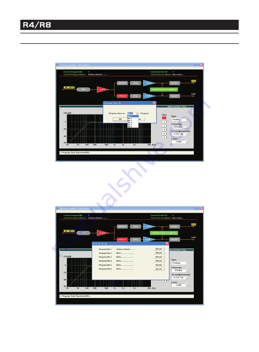
3.2>User also may save the parameters in the device, total max six programs may be saved through

Save as current program in device  under  program  menu. See Figure 7:

"

"

"

"

According to the different file source, the two ways are available for recall the existing configuration file. 
For the file saved in the computer, it may be recalled from  Open  under  File  menu. Then connect 
the equipment, choose  Download program data to device  in pop-out dialog box, see Figure 4.

"

"

"

"

"

"

Figure

7

3.3> For the files(or programs) in the device, it may be recalled through  List Program&Recall  in Program menu. 
        See Figure 8

"

"

Select the program you want to use in the pop-out dialog box, then click  Recall  button, the software 
will update the display automatically, and the device using the program that has been recalled.

"

"

Summary of Contents for R4

Page 1: ...COMPACT LINE ARRAY SOUND REINFORCEMENT SYSTEM 3G 3 MA 180327 001 β USER MANUAL ...

Page 2: ...3 Description Acoustic Features Installation Connection TABLE OF CONTENTS 20 27 Amplifier Module With DSP 28 Safety Information Warranty Technical Specifications 27 27 Software Application Guide Application Examples ...

Page 3: ...lable for use at any moment when connected to sound resource System control over each cluster at frequency response crossover point slope delay gain and limit protection can be achieved by connecting the speaker system to PC via RS 232 port Adoption of ribbon tweeters offers a wide range frequency response to up to 40kHz The tweeter s impedance and phase response curves are nearly ideal horizontal...

Page 4: ...REINFORCEMENT SYSTEM 1 00 1k 1 0k 2 0k Hz 20 1 8 0 D eg 1 0 8 3 6 3 6 1 08 1 80 2 Deg 180 150 120 90 60 30 0 30 60 90 120 150 180 500 Hz 1K 5K 10K 20K 40K dBSPL 65 70 75 80 85 90 95 100 100 Hz FREQUENCY RESPONSE PHASE RESPONSE ...

Page 5: ...10 15 20 25 dB 0 0 2 7 5 4 8 0 ms 2 00 5 00 1 k 2k 5k 1 0k 20k 150 Hz 1 1 0 d B SPL 1 8 0 D eg 9 0 1 0 8 7 0 3 6 5 0 3 6 3 0 1 0 8 1 0 1 80 1 20 50 1 00 2 00 5 00 1k 2k 5k 1 0k 2 0k Hz 10 3 WATERFALL THD Frequency Response 2nd Distortion 3rd Distortion ...

Page 6: ...40K Ohm 2 3 4 5 6 7 8 9 10 20 30 40 50 Deg 180 150 120 90 60 30 0 30 60 90 120 150 180 20 Hz 50 100 200 500 1K 2K 5K 10K 20K 40K Ohm 2 3 4 5 6 7 8 9 10 20 30 40 50 Deg 180 150 120 90 60 30 0 30 60 90 120 150 180 IMPEDANCE CURVE IMPEDANCE CURVE OF R8 IMPEDANCE CURVE OF THE RIBBON TWEETER ...

Page 7: ...90 120 150 180 210 240 270 300 330 0 30 60 90 120 150 180 210 240 270 300 330 0 30 60 90 120 150 180 210 240 270 300 330 0 30 60 90 120 150 180 210 240 270 300 330 0 30 60 90 120 150 180 210 240 270 300 330 0 30 60 90 120 150 180 210 240 270 300 330 0 30 60 90 120 150 180 210 240 270 300 330 5 HORIZONTAL DIRECTIVITY The data of horizontal directivity were collected by testing the speaker system in...

Page 8: ...0 90 120 150 180 210 240 270 300 330 0 30 60 90 120 150 180 210 240 270 300 330 0 30 60 90 120 150 180 210 240 270 300 330 0 30 60 90 120 150 180 210 240 270 300 330 0 30 60 90 120 150 180 210 240 270 300 330 0 30 60 90 120 150 180 210 240 270 300 330 0 30 60 90 120 150 180 210 240 270 300 330 6 The scale is stepped by 6dB increment The data of vertical directivity were collected by testing the sp...

Page 9: ...COMPACT LINE ARRAY SOUND REINFORCEMENT SYSTEM 7 INSTALLATION Ring Flying Frame M5 Thumb Screw M5 Small Head Screw Front Link R4 R8 Link R4 Back Link R4 Back Link R4 R8 Link ...

Page 10: ...with the edges of the two U grooves indicates successful mounting Turn R4 speaker together with its back link R4 Back Link make sure the right scale line marked on the R4 Back Link is aligned with the edge of the U groove at the back of R4 speaker The numbers marked besides each scale line indicate different splay angles Then insert the M5 thumb screw through the aligned holes of the R4 Back Link ...

Page 11: ...thumb screws accordingly 5 Demount the two M5 thumb screws at the top of the front side of R4 6 Insert the two R8 Front Links into the U grooves along the left right front edges of R4 make sure the two screw holes on both sides are aligned and then tighten the screws through the holes 7 Insert one end of the R4 R8 Link into the U groove on the back of R4 and the other end into the U groove on the ...

Page 12: ...e long flying frame into the U grooves along the left right front edges of R4 make sure the two screw holes on both sides are aligned and then thumb tighten two M5 screws through the holes Turn the R4 speaker make the scale line marked with the number of 0 on the R4 link attached to the long flying frame aligned with the bottom edge of the U groove then insert a M5 thumb screw through the two alig...

Page 13: ...11 CONNECTION Power Input Signal Input R4 Speaker Output R4 Input R4 Output R4 Input R4 Input R4 Input R4 Output R4 Output COMPACT LINE ARRAY SOUND REINFORCEMENT SYSTEM ...

Page 14: ...mplifier module embedded in the system has been made some optimization based on previous version RS 485 and USB port are added into it for computer connection it will be very convenient for user to configurate system parameters by software Built in stepless cooling fan Speed will be changed according to the temperature automatically to make sure system work stably overload protection short circuit...

Page 15: ...nect the equipment to computer by RS 232 if the computer has not the RS 232 interface you may use USB port after connection the computer will indicate that new device is found then you may install the USB driver located in driver directory of the CD Software operation guide 1 Run the software Active Speaker Controller from program menu in the windows start button the following interface will be sh...

Page 16: ...ting automatically Attention Please this operation will overwrite the current program configuration before executing this operation please make sure you really ready to load factory default settings Details of other function items such as List Program Recall and Save as current program in device under the Program menu please refer to following description 1 4 Device Modify the device information a...

Page 17: ...ata to Device must be chosen the operation execute transmitting the parameters into Device s RAM if no further save into device operation the parameters will be lost after the device power off If user chose Upload Program Data From Device it will load the current program that stored in device to PC Select the left device that you will want to connect click the Connect button to start connecting At...

Page 18: ... button and executing those operation that you want 3 Recall or Save the configuration file When the device used in different places the different configuration file are necessary Two ways are available for user to recall or save the configuration file 3 1 Save as a file When user finish the adjustment the parameters may be saved as a file into PC through Save As in the file menu see Figure 6 When...

Page 19: ...existing configuration file For the file saved in the computer it may be recalled from Open under File menu Then connect the equipment choose Download program data to device in pop out dialog box see Figure 4 Figure 7 3 3 For the files or programs in the device it may be recalled through List Program Recall in Program menu See Figure 8 Select the program you want to use in the pop out dialog box t...

Page 20: ... and device name After connecting it may be changed through clicking Edit current device information in device menu See Figure 9 Attention ID number is only available for number 1 10 that s to say only max 10 device may be connected one RS 485 Net The max length of name is 14ASCII characters Figure 9 5 Change the current program name Click Program menu choose Edit current program name to change th...

Page 21: ...the adjustment of parameters the current parameters may be saved into the device for the next power on operation If user does not save the program into device all the changes based on previous parameters will not be saved Choose Disable communications under communications menu to disconnection Please see the figure 11 ...

Page 22: ...e command Please see details as below example 1 After uploading the Program No 1 from the device to the PC then modify those parameters that you want then select the Save As Current Program In Device command in Program Menu 2 Then select the Program Number that will be saved into device Then click OK button the Program No 1 has been saved as Program No 2 and the current program auto changed to No ...

Page 23: ...RCEMENT SYSTEM 21 APPLICATION EXAMPLES 3 Then select Edit Current Program Name command in Program menu 4 Then on the Set Current Program Name interface edit the program name as you want Changed to my concert hall as the bellow figure ...

Page 24: ...22 APPLICATION EXAMPLES 5 Click OK button thus the Current Program Name on the main interface has been changed to my concert hall 6 Select List Program Recall command in Program menu the result in the program list of the device now as bellow figure ...

Page 25: ...r device You may modify the program name on disconnection status and save as another file Then download the new config file into device then save as another program or current program into device Operation Example Steps 1 After upload the Program No 3 from the device to the PC then modify some parameters that user want to do if adjust OK then select Disable Communications command in Communications...

Page 26: ...D REINFORCEMENT SYSTEM 24 APPLICATION EXAMPLES Edit Program Name to my modified program 3 then click OK button 3 Then select Save As command in File menu 4 In the File Name N frame input next hall asc then click Save S button ...

Page 27: ... as program in device 1 After downloading the config file into DEVICE only to RAM before select Save As Current Program In Device command the parameters have not saved into FLASH ROM 2 Select Save As Current Program In Device command in Program menu 3 Then select the No for example No 4 that you want to save in ...

Page 28: ...TEM 26 APPLICATION EXAMPLES Click OK button then the parameters of config file next_hall asc have been saved as program No 4 in device The Current Program No and the Current Program Name are corresponding to File as bellow figure List as below ...

Page 29: ...ls are included in the Limited Warranty R8 Accessories are guaranteed against malfunction statement R4 R8 hardware and rigging accessories is guaranteed against malfunction due to defects in materials or workmanship for a period of one 1 year from the date of original purchase Additional details are included in the Limited Flying Hardware including enclosure mounted Warranty statement LIMITED WARR...

Page 30: ...rsion Vertical Dispersion Max Constant Power Output For Mid high Range Max Constant Power Output For Mid low Range 4dBu Line In Sensitivity Driver Dimensions WxDxH Net Weight TECHNICAL SPECIFICATIONS 608 536 1100W Power Max Power Suply Different AC input versions are available for this product please pay attention to the AC mark on the product 240V 230V 220V T6 3AL 50Hz 60Hz 120V 115V 110V 100V T1...

Page 31: ...www beta3pro com ...

Reviews: