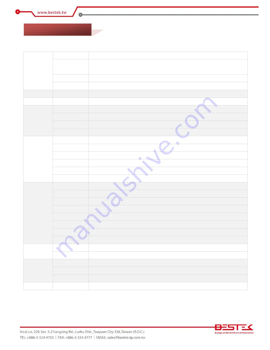
BESTEK BNX-A61B User Manual Download Page 8


Core Engine 

Chipset 

Intel®  H61 PCH 

Processor 

Support Intel®  Gen-2/3 Core i3, i5, i7, Pentium® , Celeron®  Processor 

Single LGA1155 Processor Socket 

Memory 

2x DDR3 1066/1333 DIMM Slots, up to 16GB, Non-ECC/Non-Buffered Memory Module 

Display 

Intel®  HD Graphics 2000/2500/4000 

Ethernet 

Controller 

Onboard 2x Realtek RTL8111F PCIe GbE Controllers, Support WOL and PXE 

Storage 

SATA 

4x SATA2 Ports 

Expansion 

PCIe X16 

1x 

PCIe X1 

2x 

PCI 

4x 

miniPCIe 

1x Full-sized 

Edge I/O 

PS/2 

2x PS/2 for Keyboard and Mouse 

COM 

1x DB9 RS-232, 1x DB9 RS-232/422/485 

Display 

1x DB15 VGA + 1x DVI-D 

LAN 

2x RJ45 GbE 

USB 

4 x USB 2.0 

Audio 

3x Audio Jacks (ALC887) 

Internal I/O 

Front Panel 

1x Front Panel Switch/LED Header 

LPT 

1x Parallel Box Header 

COM 

4x RS-232 Pin Headers 

USB 

5x USB2.0 Pin Headers 

DIO 

8x DIO Pin Header 

TPM 

1x TPM Header 

Chassis Intrusion 

1x 2-pin Pin Header 

Fan 

3x Fan Connectors 

Other 

H/W Monitoring 

Monitor temperature, voltage, and fan speed, auto-throttling control at CPU overheat 

WDT 

1 sec increment from 1 to 255 sec 

Environment 


Operating Temp. 

0

o

C ~ 60

o

Storage Temp. 

-20

o

C ~ 70

o

Humidity 

10% ~ 90% (Non-Condensing) 

Mechanical 

Dimension 

305mm (W) x 244mm (D) 


1.2 Specifications 


Summary of Contents for BNX-A61B

Page 1: ...1 Embedded Board BNX A61B Always at the forefront of innovation User Manual...

Page 2: ...t 15 of the FCC rules These limits are designed to provide reasonable protection against harmful interference when the equipment is operated in a residential installation This equipment generates uses...

Page 3: ...electrical discharge can damage computer components without causing any signs of physical damage You must take extra care in handling them to ensure against electrostatic build up 1 To prevent electr...

Page 4: ...pe recommend by the manufacturer Dispose of used batteries according to local ordinance Before using the system prepare basic system components If the system comes as a barebone that is none of the ke...

Page 5: ...ing Jumpers 12 2 4 Back Panel Connectors 13 2 5 Location of Jumpers and Connectors 14 Chapter 3 Operation 3 1 System Memory 25 3 2 Installing Memory 25 3 3 Installing LGA1155 Intel Core i CPU Heat Sin...

Page 6: ...6 Chapter 1 General Information...

Page 7: ...support and integrated HD graphic controller Intel Gen 2 3 LGA1155 Sandybridge Ivybridge Processor Two DDR3 RAM Slots up to 16GB Four SATA Ports 4 SATA 2 0 Two Display Ports DB15 VGA DVI D Six Series...

Page 8: ...oard and Mouse COM 1x DB9 RS 232 1x DB9 RS 232 422 485 Display 1x DB15 VGA 1x DVI D LAN 2x RJ45 GbE USB 4 x USB 2 0 Audio 3x Audio Jacks ALC887 Internal I O Front Panel 1x Front Panel Switch LED Heade...

Page 9: ...9 Figure 1 1 Board Layout of BNX A61B 1 3 Board Layout...

Page 10: ...10 Chapter 2 Preparation...

Page 11: ...ts Humid environment tend to have less static electricity than dry environments A grounding strap is warranted whenever danger of static electricity exists Computer components and electronic circuit b...

Page 12: ...f you remove the jumper cap or place the jumper cap on just one pin the jumper is OPEN Please see the following illustrations The illustrations on the right show a 2 pin jumper When the jumper cap is...

Page 13: ...Mouse Green 2 DB9 RS 232 422 485 Configurable via BIOS 3 DB15 VGA 4 LAN1 LAN2 5 Line In Jack 6 Line Out Jack 7 Microphone Jack 8 4 USB 2 0 9 DVI D 10 DB9 RS 232 11 PS 2 Keyboard Purple 2 4 Back Panel...

Page 14: ...14 2 5 Locations Of Jumpers and Connectors...

Page 15: ...ocket 6 DDR3 DIMM slots 7 Standby Power LEDs SB_PWR1 2 8 Clear RTC RAM 3 pin CLRTC 9 Chassis intrusion connector 4 1 pin CHASSIS1 10 Direct connector 2 pin DRCT1 11 AT Mode selection 3 pin ATMODE 12 S...

Page 16: ...16 Clear CMOS Jumper COM2 RI pin Power Selection Jumper 2 6 Jumpers...

Page 17: ...17 AT ATX Mode Selection Jumper...

Page 18: ...18 24 pin ATX Power Connector 4 pin CPU Chassis Fan Connector 2 7 Internal Connectors...

Page 19: ...19 25 pin LPT Connector 9 pin System Panel Connector 7 pin SATA Connector...

Page 20: ...20 19 pin TPM Connector 9 pin USB 2 0 Connector 4 pin Chassis Intrusion Connector...

Page 21: ...21 9 pin Serial Port Connector 10 pin Digital I O Connector 2 pin DirectKey Connector...

Page 22: ...22 Chapter 3 Operation...

Page 23: ...up the two side tabs on the slot 2 Make sure the Key on Memory module and socket are perfectly matched and add slowly the RAM module into the socket along the plastic guides at both ends 3 Make sure...

Page 24: ...24 4 To remove the Memory modules please push the tabs outwards and the memory modules will be automatically disengaged...

Page 25: ...cidentally damage the socket simply by adjusting the position of the CPU Please follow the installation instructions as shown below Step A Opening the Socket 1 Push the Socket Lever down and away from...

Page 26: ...with the Pin 1 chamfer on the socket 3 Make sure that the notches on the processor align with the posts on the socket 4 Lower the processor straight down without tilting or sliding it in the socket St...

Page 27: ...processor socket Ensure that the fan power cable is on the side closet to the processor fan header 2 Align the fasteners with the corresponding board holes four of them Ensure that the fasteners slots...

Page 28: ...the 24 pin ATX Power Connector on the blue connector and 4 pin 12Vdc Power Connector on the red connector In case the 12Vdc Power Connector is not added power supply will be triggered but the motherbo...

Page 29: ...al PCI Yellow 1 PCIe X1 Slot PCIe 2 0 X1 Signal Good for PCIe X1 Card White 1 PCIe X16 Slot PCIe 2 0 3 0 X16 Signal Speed of PCIe 2 0 or 3 0 bus is determined by CPU Good for all PCIe Cards 2 Shutdown...

Page 30: ...ni Card Installation A If a screw is found in the stand off please remove the screw B Align the notch in the card with the socket key and insert the card at a slightly upward angle as shown C Push dow...

Page 31: ...31 Chapter 4 BIOS Setup...

Page 32: ...gramshouldbeexecuted underthefollowing conditions Whenchanging thesystem configurations Whena configuration erroris detectedbythe systemandyouare promptedto make changes to the Setup program Whenreset...

Page 33: ...the POST TO ENTER SETUP BEFORE BOOT PRESS CTRL ALT ESC OR DEL KEY Pressthe Del keyor pressthe Ctrl Alt and Esc keysto enterSetup The online description of the highlighted setup item is displayed at th...

Page 34: ...ced Advanced system settings Boot System boot configuration Tool Other functions Exit Exit options as well as loading optimal defaults System Language English Set the BIOS language System Date Day xx...

Page 35: ...Enable Disable CPU to throttling Hyper threading Enabled Enable Disable Hyper Threading function Available only when the installed Intel Processor supports this feature Active Processor Cores All Set...

Page 36: ...SATA Configuration While entering Setup BIOS automatically detects all connected SATA devices In case no SATA device is attached to a particular SATA Port Not Present message will be prompted SATA Mo...

Page 37: ...ixed at 64MB USB Configuration Legacy USB Support Enabled Enable Disable the support for USB devices on legacy operating systems Disabled The USB devices can be used only for the BIOS setup program Au...

Page 38: ...Configure the operation mode of COM2 as RS 232 422 485 APM AT ATX Power Type ATX Mode Set the power mode to AT ATX This will directly affect the Restore AC Power Loss setting Restore AC Power Loss Po...

Page 39: ...Use and keys to adjust the time Network Stack Network Stack Disabled Enable Disable UEFI network stack Ipv4 PXE Support Enabled At disabled IPV4 PXE boot option will not be created This is available...

Page 40: ...is given CPU Q Fan Control Enabled Enable Disable CPU Q Fan control feature CPU Fan Profile Standard Set the appropriate performance level of the CPU fan Standard CPU fan speed is adjusted by the CPU...

Page 41: ...is adjusted by the chassis temperature Silent Minimize the chassis fan speed for the least noisy operation Turbo Maximize chassis fan speed for the best performance This is available only when Chassis...

Page 42: ...lay time from 0 sec 10 sec Bootup NumLock State On On Set NumLock to On at power on Off Set NumLock to Off at power on Wait for F1 If Error Disabled Enabled to let system wait for the F1 key to be pre...

Page 43: ...gacy OpRom first Legacy OpRom first UEFI driver first Ignore Boot from Storage Devices Legacy OpRom first Both Legacy OpRom first Both UEFI first Legacy OpRom first UEFI driver first Ignore Boot from...

Page 44: ...44 EZ Flash 2 Utility Run EZ Flash 2 for BIOS update SPD Information DIMM Slot DIMM_A1 Displays the SPD information of the DIMM module installed on the selected slot 4 8 The Tool Menu...

Page 45: ...it BIOS setup menu and a confirmation window will pop up Select Yes at next confirm Discard Changes Exit Use this or press ESC to discard all the changed values and exit the BIOS setup menu and a conf...

Reviews: