background image

- 23 -

PREPARE LA CAMPANA

Sacar la campana de l’embalaje y controlar
el contenido.
Recivireis:
1 - Campana
1 - Casquillo con 4 Tornillos de montaje (3,9 x

9,5mm cabeza redonda)

1 - Bolsita (B080810511) con:

4 - Tornillos de montaje (4,2 x 15mm

cabeza redonda)

2 - Tornillos de montaje (M4 x 30mm

cabeza redonda)

1 - Instrucciones para instalación
1 - Garantia

4 TORNILLOS DE
MONTAJE

(3,9 x 9,5mm cabeza
redonda)

CASQUILLO

4 TORNILLOS DE
MONTAJE

(4,2 x 15mm cabeza
redonda)

2 TORNILLOS DE
MONTAJE

(M4 x 30mm cabeza
redonda)

Summary of Contents for PK22

Page 1: ... 1 BEST BY BROAN P O Box 140 Hartford WI 53027 Model PK22 ENGLISH 3 FRANÇAIS 12 ESPAÑOL 21 ...

Page 2: ... 2 ...

Page 3: ...ns must always be vented to the outdoors 7 Do not use this unit with any solid state speed control device 8 To reduce the risk of fire use only steel ductwork 9 This unit must be grounded TO REDUCETHE RISK OF A RANGETOP GREASE FIRE A Neverleavesurfaceunitsunattendedathighsettings Boiloverscausesmokingandgreasyspillovers thatmayignite Heatoilsslowlyonlowormediumsettings B AlwaysturnhoodONwhencookin...

Page 4: ...heated The motor will restart when it cools down If the motor continues to shut off and restart have the hood serviced 7 For best capture of cooking impurities the bottom of the hood should be a minimum of 24 and a maximum of 30 above the cooking surface 8 Two installers are recommended because of the large size and weight of this hood 9 Please read specification label on product for further infor...

Page 5: ... Screws 3 9 x 9 5mm Pan Head 1 Parts Bag B080810511 containing 4 Mounting Screws 4 2 x 15mm Pan Head 2 Mounting Screws M4 x 30mm Pan Head 1 Installation Instructions 1 Warranty Card 4 MOUNTING SCREWS 3 9 x 9 5mm Pan Head DISCHARGE COLLAR 4 MOUNTING SCREWS 4 2 x 15mm Pan Head 2 MOUNTING SCREWS M4 x 30mm Pan Head ...

Page 6: ...will reduce the performance of the hood Use as few of them as possible 4 Use duct tape to seal the joints between ductwork sections 5 Install a roof or wall cap Connect 8 round metal ductwork to cap and work back towards hood location ROOF CAP 8 ROUND DUCT WALL CAP HOOD 24 TO 30 ABOVE COOKING SURFACE 8 ROUND ELBOW INSTALL DISCHARGE COLLAR Attach the discharge collar onto the hood it must be attach...

Page 7: ...ehind filters with bushing so they do not protrude externally 3 Insert the hood and attach it temporarily using the 2 mounting screws M4x30mm Pan Head 4 After unit is inserted and is flush with bottom of opening secure the hood with 4 mounting screws 4 2x15mm Pan Head BUSHING FRAME TOTAL OF 2 2 MOUNTING SCREWS 4 MOUNTING SCREWS 2 MOUNTING SCREWS M4x30mm 4 MOUNTING SCREWS 4 2x15mm METAL OR OTHER NO...

Page 8: ...ing box 3 Feed 6 of power cable through the knockout opening and secure cable to the wiring box with an appropriate connector 4 Make electrical connections Connect white to white black to black and green to green 5 Replace wiring box cover and screws Make sure that wires are not pinched between cover and box WIRING BOX COVER CONNECT DUCTWORK 1 Use 8 round metal duct to connect the duct connector o...

Page 9: ...e a non scratching household cleanser or stainless steel polishing powder with a little water and a soft cloth For stubborn cases use a plastic scouring pad or soft bristle brush together with cleaser and water Rub lightly in direction of polishing lines or grain of the stainless finish Avoid using too much pressure which may mar the surface DO NOT allow deposits to remain for long periods of time...

Page 10: ...speed control The blower must be turned on and off using this switch The blower speed control changes the run ning speed of the blower 1 2 3 The pilot lamp lights up whenever the blower is on HEAT SENTRY Your hood is equipped with a HEAT SENTRY thermostat This thermostat is a device that will turn on or speed up the blower if it senses excessive heat above the cooking surface 1 If blower is OFF it...

Page 11: ...es do not allow limitation on how long an implied warranty lasts so the above limitation may not apply to you BROAN S OBLIGATION TO REPAIR OR REPLACE AT BROAN S OPTION SHALL BETHE PURCHASER S SOLE AND EXCLUSIVE REMEDY UNDER THIS WARRANTY BROAN SHALL NOT BE LIABLE FOR INCIDENTAL CONSEQUEN TIAL OR SPECIAL DAMAGES ARISING OUT OF OR IN CONNECTION WITH PRODUCT USE OR PERFORMANCE Some states do not allo...

Page 12: ...irversl extérieur 7 N utilisez pas cet appareil avec un appareil contrôlant la vitesse à état solide 8 Afindediminuertoutrisqued incendien utilisezquedesconduitsenmétal 9 Votre appareil doit être relié à la terre ATTENTION POUR REDUIRE LES RISQUES D INCENDIE DES MATIERES GRASSES QUI SONT ENTRAIN DE CUIRE A Ne laissez jamais ni vos éléments chauffants ni vos casseroles ou poêles sur le feu sans les...

Page 13: ...au moteur et de rendre les rotors bruyants et ou non équilibrés évitez que les sprays pour murs secs la poussière de construction entrent en contact avec la partie électrique 6 Le moteur de votre hotte a un thermostat qui éteindra automatiquement le moteur s il est surchauffé Le moteur se remettra en marche lorsqu il se sera refroidi Si le moteur continue à s éteindre et à se remettre en marche fa...

Page 14: ... 4 Vis d assemblage 3 9 x 9 5mm Tête ronde 1 Sachet B080810511 avec 4 Vis d assemblage 4 2 x 15mm Tête ronde 2 Vis d assemblage M4 x 30mm Tête ronde 1 Instructions pour l installation 1 Garantie 4 VIS D ASSEMBLAGE 3 9 x 9 5mm Tête ronde COLLIER D EVACUATION 4 VIS D ASSEMBLAGE 4 2 x 15mm Tête ronde 2 VIS D ASSEMBLAGE M4 x 30mm Tête ronde ...

Page 15: ...e votre hotte En utiliser le moins possible 4 Rendez les jonctions du tuyau hermétiques au moyen d un ruban pour tuyaux 5 Installez un couvercle sur le toit ou au mur Reliez un tuyau en métal rond de 8 au couvercle et faites le aller jusqu à l emplacement de votre hotte COUVERCLE DU TOIT TUYAU ROND DE 8 COUVERCLE DU MUR COUDE ROND DE 8 HOTTE DE 24 À 30 AU DESSUS DU PLAN DE CUISSON INSTALLATION DU ...

Page 16: ... attention pour qu elles ne dépassent pas vers l extérieur 3 Posez la hotte et fixez la provisoirement en serrant les 2 vis d assemblage M4x30mm Tête ronde 4 Une fois la hotte installée au ras de la partie basse de l ouverture fixez la hotte en utilisant 4 vis d assemblage 4 2x15mm Tête ronde ENCADREMENT ISOLANT 2 AU TOTAL 2 VIS D ASSEMBLAGE 4 VIS D ASSEMBLAGE 2 VIS D ASSEMBLAGE M4x30mm Tête ronde...

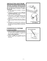
Page 17: ...u et fixez le câble à la boîte de connexion au moyen d un connecteur approprié 4 Faites le raccordement électrique Reliez le blanc au blanc le noir au noir et le vert au vert 5 Remettez le couvercle de la boîte de connexion et les vis Assurez vous que les fils se sont pas coincés entre le couvercle et la boîte CONNEXION DU SYSTEME D EVACUATION 1 Reliez le connecteur du tuyau qui se trouve sur votr...

Page 18: ...lisez un nettoyant domestique non abrasif ou de la poudre pour l acier inoxydable et un peu d eau et un chiffon doux Dans les cas difficiles utilisez une éponge en plastique ou une brosse douce avec du nettoyant et de l eau Frottez légèrement en suivant la direction du polissage ou du grain de l acier inoxydable Evitez de frotter trop fort afin de ne pas abîmer la surface NE LAISSEZ PAS les taches...

Page 19: ...e établie par le bouton réglant la vitesse Le ventilateur est mis en marche et arrêté au moyen de cet interrupteur Le bouton réglant la vitesse change la vitesse de fonctionnement du ventilateur 1 2 3 Le voyant lumineux s allume quand le ventilateur fonctionne HEAT SENTRYMC Votre hotte est munie d un thermostat HEAT SENTRYMC Ce thermostat est un dispositif qui actionnera ou augmentera la vitesse d...

Page 20: ...lation défectueuse ou bien une installation ne respectant pas les instructions d installation recommandées La durée de toute garantie implicite est limitée à un an comme cela est spécifié dans la garantie explicite Quelques états ne permettent pas de limites quant à la durée d une garantie implicite par conséquent la limitation indiquée ci dessus peut ne pas vous concerner L OBLIGATION DE REPARER ...

Page 21: ... desalojar al exterior 7 No use esta unidad con dispositivo de control de la velocidad a estado sólido 8 Para evitar el riesgo de incendio use solamente conductos de metal 9 Esta unidad tiene que ser conectada a tierra PARA EVITAR EL RIESGO DE FUEGO POR ALTO NIVEL DE GRASA A Nunca abandone los quemadores con el fuego alto La cocción causa humo y restos de grasa que pueden arder Caliente el aceite ...

Page 22: ...nivel de sobrecarga térmica que apaga automáticamente el motor cuando se ha recalentado excesivamente El motor se pone de nuevo en fincionamento cuando la temperatura baja Si el motor comienza a encenderse y a apagarse deberá hacer una revisión de éste 7 Para limpiar mejor las impurezas al cocinar la parte inferior de la campana debe estar a unatemperaturamínimade24gradosymáximade30gradospordebajo...

Page 23: ...x 9 5mm cabeza redonda 1 Bolsita B080810511 con 4 Tornillos de montaje 4 2 x 15mm cabeza redonda 2 Tornillos de montaje M4 x 30mm cabeza redonda 1 Instrucciones para instalación 1 Garantia 4 TORNILLOS DE MONTAJE 3 9 x 9 5mm cabeza redonda CASQUILLO 4 TORNILLOS DE MONTAJE 4 2 x 15mm cabeza redonda 2 TORNILLOS DE MONTAJE M4 x 30mm cabeza redonda ...

Page 24: ...nor número de ellos posible 4 Use une cinta para precintar las juntas entre las partes del entubado 5 Instale una cubierta ó una tapa Una el tubo de metal de 8 de diámetro a la cubierta y retroceda hasta la posición de la campana TAPA PARED TUBO DE 8 DE DIÁMETRO CUBIERTA DEL TEJADO MANGUITO DE 8 DE DIÁMETRO 24 A 30 POR ENCIMA DE LA ZONA DE COCCIÓN CAMPANA VERSIÓN ASPIRANTE INSTALACION DEL CASQUILL...

Page 25: ...no sobresalgan al exterior 3 Colocar la campana y sujetarla provisionalmente enroscando los 2 tornillos para el montaje M4x30mm cabeza redonda 4 Tras montar la campana y alinearla con la parte inferior de la abertura sujetarla con 4 tornillos para el montaje 4 2x15mm cabeza redonda ARMAZÓN AISLANTE TOTAL DE 2 4 TORNILLOS PARA EL MONTAJE VER DIMENSIONES DEL CORTE 2 TORNILLOS PARA EL MONTAJE M4x30 c...

Page 26: ...larlauntécnicoelectri cista siguiendo las normas nacionales y locales 1 Quite la rejilla para acceder al interior de la campana 2 Quite la tapa de la caja de conexión eléctrica y saque un cable 3 Suministre 6 de cable eléctrico al extremo y sujete el cable a la caja de conexión eléctrica con un conector adecuado 4 Haga las conexiones eléctricas una blanco con blanco negro con negro y verde con ver...

Page 27: ...las manchas o restos de grasa que persistan use un producto químico doméstico que no raye ó un limpiador para acero inoxidable con poca agua y un paño suave Si las manchas persisten use un estropajo y un cepillo de cerdas suaves con un producto limpiador y agua Frote suavemente en el sentido del pulido o de las vetas del remate del inoxidable No apriete demasiado porque podría dañar la superficie ...

Page 28: ...o la temperatura disminuye a un nivel normal el ventilador vuelve a la función de origen AVERTENCIA El HEAT SENTRYmr termostato puede comenzar a funcionar al igual si la campana esta parada En este caso es imposible parar el ventilador con los interruptores Si usted para la campana halago a partir del panel eléctrico principal LAMPARAS HALOGENAS Este tipo de campana necesita dos 2 ó cuatro 4 lámpa...

Page 29: ...stalación que no se ajuste a las instrucciones de montaje indicadas Le duración de la garantía se limita al periodo de un año como está especificado en la garantía explicita Algunos paises no permiten un limite en la duración de la garantía implicita si es asi en su caso esta limitación arriba indicada podría no aplicarse LA PRESENTE GARANTIA CUBRIRA EXCLUSIVAMENTE AL COMPRADOR LOS SERVICIOS DESCR...

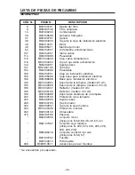
Page 30: ...66 B08086668 Circuit Board 195 BE3402994 Lamp Support 90 cm models 195 BE3402999 Lamp Support 120 cm models 196 BE3332407 Reflector 90 cm models 196 BE3345185 Reflector 120 cm models 199 B02300688 Ceramic Insulator 200 B02009103 Lamp Protection 202 B03292290 Lead 208 B02300783 Transformer 230 B03292937 Switch Board Box Cover 234 BE3341636 Controls Protection 250 B02009102 Ring Nut 415 B03292169 Le...

Page 31: ...086668 Circuit imprimé installation electrique 195 BE3402994 Support lampes modèles 90cm 195 BE3402999 Support lampes modèles 120cm 196 BE3332407 Réflecteur modèles 90cm 196 BE3345185 Réflecteur modèles 120cm 199 B02300688 Support de ceramique 200 B02009103 Protection lampes 202 B03292290 Serre cable 208 B02300783 Trasformateur 230 B03292937 Couvercle boîte commandes 234 BE3341636 Protection comma...

Page 32: ... B08086668 Base para instalación electrica 195 BE3402994 Soporte de la lámpara modelo 90 cm 195 BE3402999 Soporte de la lámpara modelo 120 cm 196 BE3332407 Reflector modelo 90 cm 196 BE3345185 Reflector modelo 120 cm 199 B02300688 Soporte de céramica de la lámpara 200 B02009103 Protección de la lámpara 202 B03292290 Sujeta cabos 208 B02300783 Trasformador 230 B03292937 Tapa de la caja mandos 234 B...

Page 33: ... 33 SERVICE PARTS LISTE PIECES DE RECHANGE LISTA DE PIEZAS DE RECAMBIO MODEL PK22 ...

Page 34: ... 34 ...

Page 35: ... 35 ...

Page 36: ... 36 04306932 1 ...

Reviews: