56
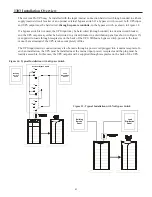
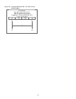
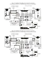
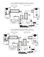
Figure 32: Installation Wiring Diagram for Axxium Pro Systems with
No External Bypass (L1, N), Non-isolated Output, and Universal Power Modules
• 220 Input, 220 Output
• 240 Input, 240 Output
• 230 Input, 230 Output
N
L1
Per Local Code
Note 1
Note 4
TO
LOADS
Note 4
Note 9
1
3
LINE INPUT
X1
+DC
X2
N
-DC
OUTPUT POWER
2
Note 8
Note 9
N
L1
Note 7
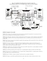
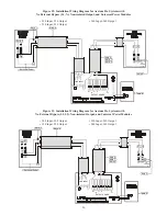
Figure 33: Installation Wiring Diagram for Axxium Pro Systems with
No External Bypass (L1, L2), Non-isolated Output, and Universal Power Modules
• 208 Input, 208 Output
• 230 Input, 230 Output
• 220 Input, 220 Output
• 240 Input, 240 Output
L2
L1
Per Local Code
Note 1
Note 4
TO
LOADS
Note 4
Note 9
1
3
LINE INPUT
X1
+DC
X2
N
-DC
OUTPUT POWER
2
Note 8
Note 9
L2
L1
Note 7

