48
1308 UPS Output Wiring Connections
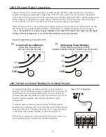
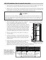
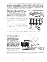
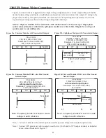
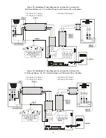
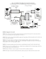
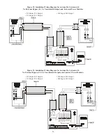
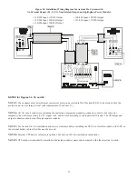
Figures on this and the next page describe output wiring configurations for various output voltages. Find the
desired output voltage and single- or split-phase configuration below, and connect the output AC wiring to the
proper Axxium Pro system power terminals. You must also set the operating menu parameter 7-3-4 for the
required output voltage as shown in the wiring configuration drawings.
NOTE: All power modules in the Axxium Pro UPS cabinet must be of the same type: Single-phase
(universal) modules have white labels; split-phase modules have blue labels. Outputs for each type of
module must be wired differently.
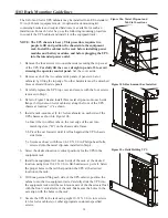
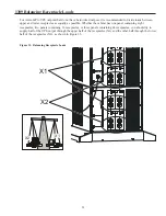
X2
X1
N/-DC
50 or 60 Hz
208, 220, 230 or 240 V Out *
Parameter 7-3-4 set to 208, 220,
230, or 240, as required.
X
X
*
L1
L2/N
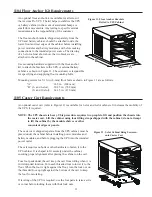
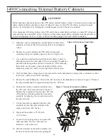
X2
X1
N/-DC
50 or 60 Hz
100/200, 110/220, 127/220,
120/208, or 120/240 V Out
Parameter 7-3-4 set to 200, 220,
208, or 240, as required.
X
X
X
200, 220
100, 110, 127,
208, or 240
or 120
100, 110, 127, or 120
L2
L1
N
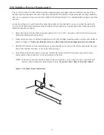
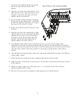
X1
X3
X0
X2
50 or 60 Hz
208, 220, 230 or 240 V Out *
with Isolated Output Option
Parameter 7-3-4 set to 208, 220, 230,
or 240, as required.
Note: If required, provide N-G bond to create
voltage to earth reference.
X
X
N-G Bond
*
L1
N
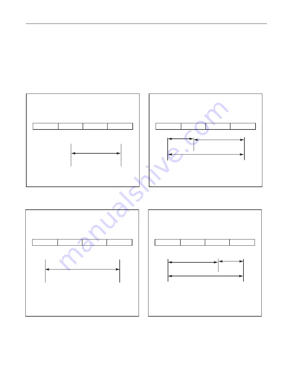
X1
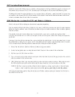
X3
X0
X2
50 or 60 Hz
110/220 or 120/240 V Out
with Isolated Output Option
Parameter 7-3-4 set to 220 or 240,
as required.
Note: If required, provide N-G bond to create
voltage to earth reference.
X
X
X
N-G Bond
110 or 120
110 or 120
220 or 240
L1
N
L2
Note 1: X3 is for cabinets with isolation options, used for special voltage with receptacle options only.
Note 2 Connect UPS green and yellow neutral-to-earth wire (N-G bond) to UPS output terminal as indicated
above and as illustrated in Figure 17.
Figure 22a. Universal Modules with Non-isolated Output
Figure 22c. Universal Modules With 2-wire Plus Ground
Isolated Output
Figure 22d. Universal Modules With 3-wire Plus Ground
Isolated Output
Figure 22b. Split-phase Modules with Non-isolated Output

