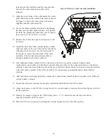
46
1307 UPS Installation with an External Bypass Switch
1. Mount the bypass switch within sight of the UPS. If you do not have a Best Power bypass switch or the fuse
box or panel is out of sight, you must install a separate disconnect switch next to the UPS.
2. Remove the six screws in the bypass switch front panel and remove the panel. Remove any packing material
inside the bypass switch. Then, remove knockouts in the bottom of the bypass switch for AC Line Input, AC
to UPS Input, AC from UPS Output, and AC to the UPS-protected equipment (loads).
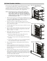
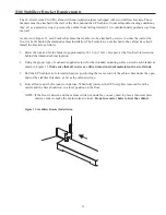
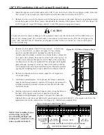
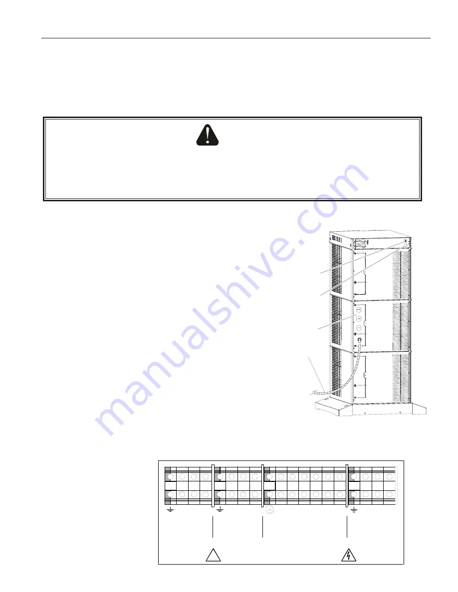
3. Remove the rear panels of the UPS (top one on 3- or 6-slot; top
two on 9- and 12-slot), as shown in Figure 18. The entrance
panel (A) contains knockout openings for entrance and exit
conduits and, if included, conduit to an external battery cabinet (B).
In 3- and 6-slot cabinets, this panel is on the back of the top bay. In
9- and 12-slot cabinets, this panel is on the back of the second bay
(as shown here). Wiring for optional EPO and bypass input signals
passes through opening (C) at the top back of the cabinet. Wiring
for an optional generator input signal must pass through a separate
opening (D). Installing this wiring is described in Steps 10 and 11.
4. Remove the knockouts in the entrance panel for AC input and
AC output wiring.
5. Install the conduit adapters. AC Input and AC Output conductors
must be run through separate conduits. UPS output circuits must be
installed in dedicated conduit systems and not shared with other
electrical circuits.
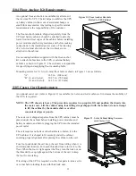
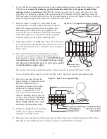
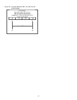
6. Find the terminal strip inside the bypass switch. Using the label on
the back of the bypass switch access panel and the proper
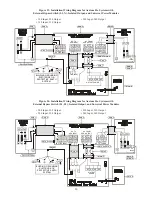
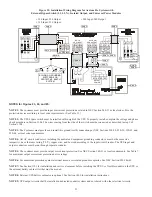
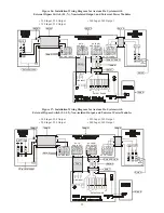
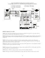
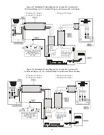
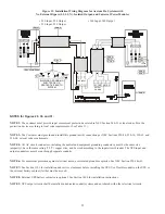
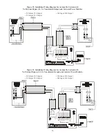
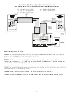
Installation Wiring Diagram (Figures 23 through 34), make the
terminal strip connections and tighten all connections as specified in Table 13. Use copper wire that is the
appropriate size for the current draw. See Figure 19, which shows a sample label.
Figure 19. Bypass Switch Wiring Label
CAUTION
To prevent electrical shock or damage to the equipment, make sure the Axxium Pro UPS is OFF before you
remove the entrance panel. The circuit breaker or disconnect switch must also be off at the AC input service
panel. Also, turn OFF the AC disconnect and bypass switches before you connect any wires to the bypass
switch terminal strip.
A
D
C
B
Figure 18. UPS Power Entrance Panel
1 2
3
5
7
11 11 12 12 13
15 16
N
4
N
6
8
9 10 10
N
N
L2
L1 L2
L2
L2
L1
L1
L1
14
AC TO UPS
PROTECTED
LOADS
AC FROM
UPS OUTPUT
LINE AC INPUT
AC TO
UPS INPUT
USE COPPER CONDUCTORS ONLY.
!
LAB-1918
REFER TO WIRING DIAGRAMS IN THE INSTALLATION MANUAL.
NOTE: After installing bypass
switch wiring, torque the
screws holding all input and
output power conductors to the
values specified in Table 13.

