41
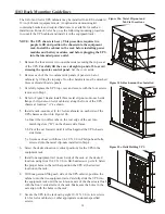
5.
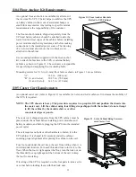
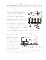
With all casters fully extended, carefully roll the cabinet down the ramp and to its intended operating
location.
6.
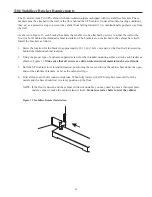
To stabilize the cabinet in its operating location, turn the four caster bolts counter-clockwise until the
cabinet rests on the floor. Place a plastic cap into each bolt access hole.
NOTE: If the floor is uneven and the cabinet is tilted or unstable, you may need to place a thin steel
plate under a corner to make the cabinet stand vertical. Do not use caster bolts to level the cabinet.
7.
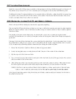
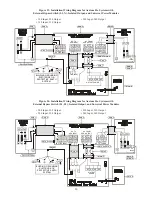
If the cabinet does not have a line (mains) power cord, install the input power conduit or cabling
between the UPS and the installation service and distribution panels. See Figures 14 and 15 and
Section 1303.
8.
If the cabinet has a line (mains) power cord, plug the cord into a mains power outlet.
9.
Refer to Section 300 for instructions to install power and battery modules.
10.
Test proper operation of external control signals and computer communication before connecting loads.
1300 UPS and Bypass Switch Installation
(for Qualified Personnel Only)
1301 Input Current Ratings
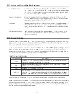
Table 11 contains the required circuit breaker ratings for hard-wired installations. Circuit breaker ratings for
units having an input line cord are determined by the current capacity of the line cord.
Table 11. Required Input Circuit Breaker Sizes (200-240 VAC, 50/60 Hz)
For redundant power module operation (N+X), increase the input current rating by 3 A for each additional level
of redundancy (3X amperes).
UPS Capacity
Circuit Breaker Rating
3 kVA
25 A
6 kVA
50 A
9 kVA
70 A
12 kVA
100 A
15 kVA
125 A
18 kVA
150 A

